modelPrescribedOutletState
Information
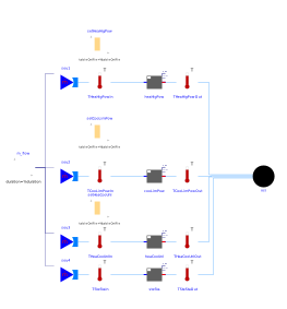
Model that is used as the base class for models that demonstrates the use of an ideal heater and an ideal cooler, or an ideal humidifier and dehumidifier.
The model on the top has almost unlimited positive capacity (Q_flow_nominal = 1.0e10 Watts),
and hence its outlet temperature always reaches the set points.
The model in the middle has a limited negative capacitiy (Q_flow_nominal = 1000 Watts), and hence
its outlet state reaches only a limited value corresponding to its
maximum negative capacity.
The model at the bottom has unlimited capacity.
At t=1000 second, the flow reverses its direction.
Each flow leg has the same mass flow rate. There are three mass flow sources as using one source only would yield a nonlinear system of equations that needs to be solved to determine the mass flow rate distribution.
Parameters
| Type | Name | Default | Description |
|---|---|---|---|
| Modelica.Units.SI.MassFlowRate | m_flow_nominal | 0.1 | Nominal mass flow rate |
Components
| Type | Name | Default | Description |
|---|---|---|---|
| Buildings.Fluid.Sources.Boundary_pT | sin | Sink | |
| Buildings.Fluid.Interfaces.PrescribedOutlet | heaHigPow | Steady-state model of the heater with high capacity | |
| Modelica.Blocks.Sources.CombiTimeTable | setHeaHigPow | Setpoint heating and humidification | |
| Buildings.Fluid.Interfaces.PrescribedOutlet | cooLimPow | Steady-state model of the cooler with limited capacity | |
| Modelica.Blocks.Sources.CombiTimeTable | setCooLimPow | Setpoint cooling and dehumidification | |
| Buildings.Fluid.Interfaces.PrescribedOutlet | heaCooUnl | Steady-state model of the heater or cooler with unlimited capacity | |
| Buildings.Fluid.Interfaces.PrescribedOutlet | steSta | Steady-state model of the heater or cooler with unlimited capacity | |
| Modelica.Blocks.Sources.CombiTimeTable | setHeaCooUnl | Setpoint cooling, heating, dehumidification and humidification | |
| Modelica.Blocks.Sources.Ramp | m_flow | Mass flow rate | |
| Buildings.Fluid.Sources.MassFlowSource_T | sou1 | Flow source | |
| Buildings.Fluid.Sources.MassFlowSource_T | sou2 | Flow source | |
| Buildings.Fluid.Sources.MassFlowSource_T | sou3 | Flow source | |
| Buildings.Fluid.Sources.MassFlowSource_T | sou4 | Flow source | |
| Buildings.Fluid.Sensors.TemperatureTwoPort | THeaHigPowIn | Temperature sensor at the inlet of heaHigPow | |
| Buildings.Fluid.Sensors.TemperatureTwoPort | THeaHigPowOut | Temperature sensor at the outlet of heaHigPow | |
| Buildings.Fluid.Sensors.TemperatureTwoPort | TCooLimPowIn | Temperature sensor at the inlet of cooLimPow | |
| Buildings.Fluid.Sensors.TemperatureTwoPort | TCooLimPowOut | Temperature sensor at the outlet of cooLimPow | |
| Buildings.Fluid.Sensors.TemperatureTwoPort | THeaCooUnlIn | Temperature sensor at the inlet of heaCooUnl | |
| Buildings.Fluid.Sensors.TemperatureTwoPort | THeaCooUnlOut | Temperature sensor at the outlet of heaCooUnl | |
| Buildings.Fluid.Sensors.TemperatureTwoPort | TSteStaIn | Temperature sensor at the inlet of steSta | |
| Buildings.Fluid.Sensors.TemperatureTwoPort | TSteStaOut | Temperature sensor at the outlet of steSta |
Contents
| Name | Description |
|---|---|
 Medium Medium |
Revisions
-
August 5, 2024, by Hongxiang Fu:
Added two-port temperature sensors to replacesta_*.Tin reference results. This is for IBPSA #1913. -
May 3, 2017, by Michael Wetter:
First implementation.