modelTank
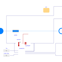
Extends from Buildings.Fluid.Interfaces.TwoPortHeatMassExchanger (Partial model transporting one fluid stream with storing mass or energy).
Information
This model implements an ice tank model whose performance is computed based on performance curves.
The model is based on the implementation of Guowen et al., 2020 and similar to the detailed EnergyPlus ice tank model ThermalStorage:Ice:Detailed.
The governing equations are as follows:
The mass of ice in the storage mice is calculated as
d SOC/dt = Q̇/(Hf mice,max)
mice = SOC mice,max
where SOC is state of charge, Q̇ is the heat transfer rate of the ice tank, positive for charging and negative for discharging, Hf is the fusion of heat of ice and mice,max is the nominal mass of ice in the storage tank.
The heat transfer rate of the ice tank Q̇ is computed using
Q̇ = Qsto,nom q*,
where Qsto,nom is the storage capacity and q* is a normalized heat flow rate. The storage capacity is
Qsto,nom = Hf mice,max,
where Hf is the latent heat of fusion of ice and mice,max is the maximum ice storage capacity.
The normalized heat flow rate is computed using performance curves for charging (freezing) or discharging (melting). For charging, the heat transfer rate q* between the chilled water and the ice in the thermal storage tank is calculated using
q* Δt = C1 + C2x + C3 x2 + [C4 + C5x + C6 x2]ΔTlmtd*
where Δt is the time step of the data samples used for the curve fitting, C1-6 are the curve fit coefficients, x is the fraction of charging, also known as the state-of-charge, and Tlmtd* is the normalized LMTD calculated using Buildings.Fluid.Storage.Ice.BaseClasses.calculateLMTDStar. Similarly, for discharging, the heat transfer rate q* between the chilled water and the ice in the thermal storage tank is
- q* Δt = D1 + D2(1-x) + D3 (1-x)2 + [D4 + D5(1-x) + D6 (1-x)2]ΔTlmtd*
where Δt is the time step of the data samples used for the curve fitting, D1-6 are the curve fit coefficients.
The normalized LMTD ΔTlmtd* uses a nominal temperature difference of 10 Kelvin. This value must be used when obtaining the curve fit coefficients.
The log mean temperature difference is calculated using
ΔTlmtd* = ΔTlmtd/Tnom
ΔTlmtd = (Tin - Tout)/ln((Tin - Tfre)/(Tout - Tfre))
where Tin is the inlet temperature, Tout is the outlet temperature, Tfre is the freezing temperature and Tnom is a nominal temperature difference of 10 Kelvin.
Usage
This model requires the fluid to flow from port_a to port_b.
Otherwise, the simulation stops with an error.
Reference
Strand, R.K. 1992. “Indirect Ice Storage System Simulation,” M.S. Thesis, Department of Mechanical and Industrial Engineering, University of Illinois at Urbana-Champaign.
Guowen Li, Yangyang Fu, Amanda Pertzborn, Jin Wen and Zheng O'Neill. An Ice Storage Tank Modelica Model: Implementation and Validation. Modelica Conferences. 2021. doi:10.3384/ecp21181177.
Parameters
| Type | Name | Default | Description |
|---|---|---|---|
| Boolean | homotopyInitialization (from TwoPortHeatMassExchanger) | true | = true, use homotopy method |
| Buildings.Fluid.Storage.Ice.Data.Tank.Generic | per | Performance data | |
| Modelica.Units.SI.SpecificHeatCapacity | cp | Medium.specificHeatCapacityCp(Medium.setState_pTX(p = Medium.p_default, T = 273.15, X = Medium.X_default)) | Specific heat capacity of working fluid |
| Assumptions | |||
| Boolean | allowFlowReversal (from PartialTwoPort) | true | = false to simplify equations, assuming, but not enforcing, no flow reversal |
| Nominal condition | |||
| Modelica.Units.SI.MassFlowRate | m_flow_nominal (from PartialTwoPortInterface) | Nominal mass flow rate | |
| Modelica.Units.SI.PressureDifference | dp_nominal (from TwoPortFlowResistanceParameters) | Pressure difference | |
| Advanced | |||
| Modelica.Units.SI.MassFlowRate | m_flow_small (from PartialTwoPortInterface) | 1E-4*abs(m_flow_nominal) | Small mass flow rate for regularization of zero flow |
| Advanced › Diagnostics | |||
| Boolean | show_T (from PartialTwoPortInterface) | false | = true, if actual temperature at port is computed |
| Flow resistance | |||
| Boolean | computeFlowResistance (from TwoPortFlowResistanceParameters) | true | =true, compute flow resistance. Set to false to assume no friction |
| Boolean | from_dp (from TwoPortFlowResistanceParameters) | false | = true, use m_flow = f(dp) else dp = f(m_flow) |
| Real | n (from TwoPortFlowResistanceParameters) | 2 | Flow exponent, n=1 for laminar, n=2 for turbulent |
| Boolean | linearizeFlowResistance (from TwoPortFlowResistanceParameters) | false | = true, use linear relation between m_flow and dp for any flow rate |
| Real | deltaM (from TwoPortFlowResistanceParameters) | 0.1 | Fraction of nominal flow rate where flow transitions to laminar |
| Dynamics › Nominal condition | |||
| Modelica.Units.SI.Time | tau (from TwoPortHeatMassExchanger) | 30 | Time constant at nominal flow (if energyDynamics <> SteadyState) |
| Dynamics › Conservation equations | |||
| Modelica.Fluid.Types.Dynamics | energyDynamics (from TwoPortHeatMassExchanger) | Modelica.Fluid.Types.Dynamics.DynamicFreeInitial | Type of energy balance: dynamic (3 initialization options) or steady state |
| Initialization | |||
| Medium.AbsolutePressure | p_start (from TwoPortHeatMassExchanger) | Medium.p_default | Start value of pressure |
| Medium.Temperature | T_start (from TwoPortHeatMassExchanger) | Medium.T_default | Start value of temperature |
| Medium.MassFraction[Medium.nX] | X_start (from TwoPortHeatMassExchanger) | Medium.X_default | Start value of mass fractions m_i/m |
| Medium.ExtraProperty[Medium.nC] | C_start (from TwoPortHeatMassExchanger) | fill(0, Medium.nC) | Start value of trace substances |
| Real | SOC_start | Start value for state of charge | |
| Dynamics heat exchanger › Conservation equations | |||
| Modelica.Fluid.Types.Dynamics | energyDynamicsHex | Modelica.Fluid.Types.Dynamics.DynamicFreeInitial | Formulation of energy balance for heat exchanger internal fluid mass |
| Modelica.Units.SI.Time | tauHex | 30 | Time constant of working fluid through the heat exchanger at nominal flow |
Connectors
| Type | Name | Default | Description |
|---|---|---|---|
| Modelica.Fluid.Interfaces.FluidPort_a | port_a (from PartialTwoPort) | Fluid connector a (positive design flow direction is from port_a to port_b) | |
| Modelica.Fluid.Interfaces.FluidPort_b | port_b (from PartialTwoPort) | Fluid connector b (positive design flow direction is from port_a to port_b) | |
| Modelica.Blocks.Interfaces.RealOutput | SOC | state of charge | |
| Modelica.Blocks.Interfaces.RealOutput | T | Temperature of the fluid leaving at port_b | |
| Modelica.Blocks.Interfaces.RealOutput | mIce | Mass of remaining ice | |
| Modelica.Blocks.Interfaces.RealOutput | Q_flow | Heat flow rate, positive during charging, negative when melting the ice |
Components
| Type | Name | Default | Description |
|---|---|---|---|
| Modelica.Units.SI.MassFlowRate | m_flow (from PartialTwoPortInterface) | port_a.m_flow | Mass flow rate from port_a to port_b (m_flow > 0 is design flow direction) |
| Modelica.Units.SI.PressureDifference | dp (from PartialTwoPortInterface) | port_a.p - port_b.p | Pressure difference between port_a and port_b |
| Medium.ThermodynamicState | sta_a (from PartialTwoPortInterface) | if allowFlowReversal then Medium.setState_phX(port_a.p, noEvent(actualStream(port_a.h_outflow)), noEvent(actualStream(port_a.Xi_outflow))) else Medium.setState_phX(port_a.p, noEvent(inStream(port_a.h_outflow)), noEvent(inStream(port_a.Xi_outflow))) | Medium properties in port_a |
| Medium.ThermodynamicState | sta_b (from PartialTwoPortInterface) | if allowFlowReversal then Medium.setState_phX(port_b.p, noEvent(actualStream(port_b.h_outflow)), noEvent(actualStream(port_b.Xi_outflow))) else Medium.setState_phX(port_b.p, noEvent(port_b.h_outflow), noEvent(port_b.Xi_outflow)) | Medium properties in port_b |
| Buildings.Fluid.MixingVolumes.MixingVolume | vol (from TwoPortHeatMassExchanger) | ||
| Buildings.Fluid.FixedResistances.PressureDrop | preDro (from TwoPortHeatMassExchanger) | Flow resistance |
Revisions
-
January 26, 2022, by Michael Wetter:
Refactored model to new architecture. Changed model to allow idealized control. Avoided SOC to be outside [0, 1]. -
December 14, 2021, by Yangyang Fu:
First implementation.