blockController
Information
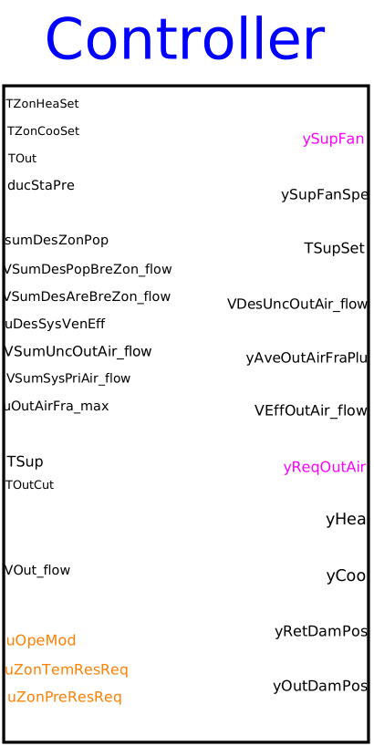
Block that is applied for multizone VAV AHU control. It outputs the supply fan status and the operation speed, outdoor and return air damper position, supply air temperature setpoint and the valve position of the cooling and heating coils. It is implemented according to the ASHRAE Guideline 36, PART 5.N.
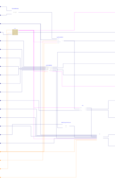
The sequence consists of five subsequences.
Supply fan speed control
The fan speed control is implemented according to PART 5.N.1. It outputs
the boolean signal ySupFan to turn on or off the supply fan.
In addition, based on the pressure reset request uZonPreResReq
from the VAV zones controller, the
sequence resets the duct pressure setpoint, and uses this setpoint
to modulate the fan speed ySupFanSpe using a PI controller.
See
Buildings.Obsolete.Controls.OBC.ASHRAE.G36_PR1.AHUs.MultiZone.VAV.SetPoints.SupplyFan
for more detailed description.
Minimum outdoor airflow setting
According to current occupany, supply operation status ySupFan,
zone temperatures and the discharge air temperature, the sequence computes the
minimum outdoor airflow rate setpoint, which is used as input for the economizer control.
More detailed information can be found in
Buildings.Obsolete.Controls.OBC.ASHRAE.G36_PR1.AHUs.MultiZone.VAV.SetPoints.OutdoorAirFlow.
Economizer control
The block outputs outdoor and return air damper position, yOutDamPos and
yRetDamPos. First, it computes the position limits to satisfy the minimum
outdoor airflow requirement. Second, it determines the availability of the economizer based
on the outdoor condition. The dampers are modulated to track the supply air temperature
loop signal, which is calculated from the sequence below, subject to the minimum outdoor airflow
requirement and economizer availability. Optionally, there is also an override for freeze protection.
See
Buildings.Obsolete.Controls.OBC.ASHRAE.G36_PR1.AHUs.MultiZone.VAV.Economizers.Controller
for more detailed description.
Supply air temperature setpoint
Based on PART 5.N.2, the sequence first sets the maximum supply air temperature
based on reset requests collected from each zone uZonTemResReq. The
outdoor temperature TOut and operation mode uOpeMod are used
along with the maximum supply air temperature, for computing the supply air temperature
setpoint. See
Buildings.Obsolete.Controls.OBC.ASHRAE.G36_PR1.AHUs.MultiZone.VAV.SetPoints.SupplyTemperature
for more detailed description.
Coil valve control
The subsequence retrieves supply air temperature setpoint from previous sequence. Along with the measured supply air temperature and the supply fan status, it generates coil valve positions. See Buildings.Obsolete.Controls.OBC.ASHRAE.G36_PR1.AHUs.MultiZone.VAV.SetPoints.SupplySignals
Parameters
| Type | Name | Default | Description |
|---|---|---|---|
| Real | samplePeriod | 120 | Sample period of component, set to the same value to the trim and respond sequence |
| System and building parameters | |||
| Boolean | have_perZonRehBox | true | Check if there is any VAV-reheat boxes on perimeter zones |
| Boolean | have_duaDucBox | false | Check if the AHU serves dual duct boxes |
| Boolean | have_airFloMeaSta | false | Check if the AHU has AFMS (Airflow measurement station) |
| Economizer | |||
| Boolean | use_enthalpy | false | Set to true if enthalpy measurement is used in addition to temperature measurement |
| Real | delta | 5 | Time horizon over which the outdoor air flow measurment is averaged |
| Real | delTOutHis | 1 | Delta between the temperature hysteresis high and low limit |
| Real | delEntHis | 1000 | Delta between the enthalpy hysteresis high and low limits |
| Economizer › Damper limits | |||
| Real | retDamPhyPosMax | 1.0 | Physically fixed maximum position of the return air damper |
| Real | retDamPhyPosMin | 0.0 | Physically fixed minimum position of the return air damper |
| Real | outDamPhyPosMax | 1.0 | Physically fixed maximum position of the outdoor air damper |
| Real | outDamPhyPosMin | 0.0 | Physically fixed minimum position of the outdoor air damper |
| Economizer PID controller | |||
| Buildings.Controls.OBC.CDL.Types.SimpleController | controllerTypeMinOut | Buildings.Controls.OBC.CDL.Types.SimpleController.PI | Type of controller |
| Real | kMinOut | 0.05 | Gain of controller for minimum outdoor air intake |
| Real | TiMinOut | 120 | Time constant of controller for minimum outdoor air intake |
| Real | TdMinOut | 0.1 | Time constant of derivative block for minimum outdoor air intake |
| Economizer freeze protection | |||
| Boolean | use_TMix | true | Set to true if mixed air temperature measurement is enabled |
| Boolean | use_G36FrePro | false | Set to true to use G36 freeze protection |
| Buildings.Controls.OBC.CDL.Types.SimpleController | controllerTypeFre | Buildings.Controls.OBC.CDL.Types.SimpleController.PI | Type of controller |
| Real | kFre | 0.05 | Gain for mixed air temperature tracking for freeze protection, used if use_TMix=true |
| Real | TiFre | 120 | Time constant of controller for mixed air temperature tracking for freeze protection. Require TiFre <= TiMinOut |
| Real | TdFre | 0.1 | Time constant of derivative block for freeze protection |
| Real | TFreSet | 279.15 | Lower limit for mixed air temperature for freeze protection, used if use_TMix=true |
| Economizer › Economizer delays at disable | |||
| Real | retDamFulOpeTim | 180 | Time period to keep RA damper fully open before releasing it for minimum outdoor airflow control at disable to avoid pressure fluctuations |
| Real | disDel | 15 | Short time delay before closing the OA damper at disable to avoid pressure fluctuations |
| Fan speed › Trim and respond for reseting duct static pressure setpoint | |||
| Real | pIniSet | 60 | Initial pressure setpoint for fan speed control |
| Real | pMinSet | 25 | Minimum pressure setpoint for fan speed control |
| Real | pMaxSet | 400 | Maximum pressure setpoint for fan speed control |
| Real | pDelTim | 600 | Delay time after which trim and respond is activated |
| Integer | pNumIgnReq | 2 | Number of ignored requests for fan speed control |
| Real | pTriAmo | -12.0 | Trim amount for fan speed control |
| Real | pResAmo | 15 | Respond amount (must be opposite in to triAmo) for fan speed control |
| Real | pMaxRes | 32 | Maximum response per time interval (same sign as resAmo) for fan speed control |
| Fan speed PID controller | |||
| Buildings.Controls.OBC.CDL.Types.SimpleController | controllerTypeFanSpe | Buildings.Controls.OBC.CDL.Types.SimpleController.PI | Type of controller |
| Real | kFanSpe | 0.1 | Gain of fan fan speed controller, normalized using pMaxSet |
| Real | TiFanSpe | 60 | Time constant of integrator block for fan speed |
| Real | TdFanSpe | 0.1 | Time constant of derivative block for fan speed |
| Real | yFanMax | 1 | Maximum allowed fan speed |
| Real | yFanMin | 0.1 | Lowest allowed fan speed if fan is on |
| Minimum outdoor airflow rate › Nominal conditions | |||
| Real | VPriSysMax_flow | Maximum expected system primary airflow at design stage | |
| Real | peaSysPop | Peak system population | |
| Supply air temperature › Temperature limits | |||
| Real | TSupSetDes | 285.15 | Design coil leaving air temperature |
| Real | TSupSetMin | 285.15 | Lowest cooling supply air temperature setpoint when the outdoor air temperature is at the higher value of the reset range and above. This should not be lower than the design coil leaving air temperature |
| Real | TSupSetMax | 291.15 | Highest cooling supply air temperature setpoint. It is typically 18 degC (65 degF) in mild and dry climates, 16 degC (60 degF) or lower in humid climates |
| Real | TOutMin | 289.15 | Lower value of the outdoor air temperature reset range. Typically value is 16 degC (60 degF) |
| Real | TOutMax | 294.15 | Higher value of the outdoor air temperature reset range. Typically value is 21 degC (70 degF) |
| Real | TSupWarUpSetBac | 308.15 | Supply temperature in warm up and set back mode |
| Supply air temperature › Trim and respond for reseting TSup setpoint | |||
| Real | delTimSupTem | 600 | Delay timer for supply temperature control |
| Integer | numIgnReqSupTem | 2 | Number of ignorable requests for supply temperature control |
| Real | triAmoSupTem | 0.1 | Trim amount for supply temperature control |
| Real | resAmoSupTem | -0.2 | Response amount for supply temperature control |
| Real | maxResSupTem | -0.6 | Maximum response per time interval for supply temperature control |
| Supply air temperature | |||
| Buildings.Controls.OBC.CDL.Types.SimpleController | controllerTypeTSup | Buildings.Controls.OBC.CDL.Types.SimpleController.PI | Type of controller for supply air temperature signal |
| Real | kTSup | 0.05 | Gain of controller for supply air temperature signal |
| Real | TiTSup | 600 | Time constant of integrator block for supply air temperature control signal |
| Real | TdTSup | 0.1 | Time constant of integrator block for supply air temperature control signal |
| Real | uHeaMax | -0.25 | Upper limit of controller signal when heating coil is off. Require -1 < uHeaMax < uCooMin < 1. |
| Real | uCooMin | 0.25 | Lower limit of controller signal when cooling coil is off. Require -1 < uHeaMax < uCooMin < 1. |
Connectors
| Type | Name | Default | Description |
|---|---|---|---|
| Buildings.Controls.OBC.CDL.Interfaces.RealInput | TZonHeaSet | Zone air temperature heating setpoint | |
| Buildings.Controls.OBC.CDL.Interfaces.RealInput | TZonCooSet | Zone air temperature cooling setpoint | |
| Buildings.Controls.OBC.CDL.Interfaces.RealInput | TOut | Outdoor air temperature | |
| Buildings.Controls.OBC.CDL.Interfaces.RealInput | ducStaPre | Measured duct static pressure | |
| Buildings.Controls.OBC.CDL.Interfaces.RealInput | sumDesZonPop | Sum of the design population of the zones in the group | |
| Buildings.Controls.OBC.CDL.Interfaces.RealInput | VSumDesPopBreZon_flow | Sum of the population component design breathing zone flow rate | |
| Buildings.Controls.OBC.CDL.Interfaces.RealInput | VSumDesAreBreZon_flow | Sum of the area component design breathing zone flow rate | |
| Buildings.Controls.OBC.CDL.Interfaces.RealInput | uDesSysVenEff | Design system ventilation efficiency, equals to the minimum of all zones ventilation efficiency | |
| Buildings.Controls.OBC.CDL.Interfaces.RealInput | VSumUncOutAir_flow | Sum of all zones required uncorrected outdoor airflow rate | |
| Buildings.Controls.OBC.CDL.Interfaces.RealInput | VSumSysPriAir_flow | System primary airflow rate, equals to the sum of the measured discharged flow rate of all terminal units | |
| Buildings.Controls.OBC.CDL.Interfaces.RealInput | uOutAirFra_max | Maximum zone outdoor air fraction, equals to the maximum of primary outdoor air fraction of all zones | |
| Buildings.Controls.OBC.CDL.Interfaces.RealInput | TSup | Measured supply air temperature | |
| Buildings.Controls.OBC.CDL.Interfaces.RealInput | TOutCut | OA temperature high limit cutoff. For differential dry bulb temeprature condition use return air temperature measurement | |
| Buildings.Controls.OBC.CDL.Interfaces.RealInput | hOut | Outdoor air enthalpy | |
| Buildings.Controls.OBC.CDL.Interfaces.RealInput | hOutCut | OA enthalpy high limit cutoff. For differential enthalpy use return air enthalpy measurement | |
| Buildings.Controls.OBC.CDL.Interfaces.RealInput | VOut_flow | Measured outdoor volumetric airflow rate | |
| Buildings.Controls.OBC.CDL.Interfaces.RealInput | TMix | Measured mixed air temperature, used for freeze protection if use_TMix=true | |
| Buildings.Controls.OBC.CDL.Interfaces.IntegerInput | uOpeMod | AHU operation mode status signal | |
| Buildings.Controls.OBC.CDL.Interfaces.IntegerInput | uZonTemResReq | Zone cooling supply air temperature reset request | |
| Buildings.Controls.OBC.CDL.Interfaces.IntegerInput | uZonPreResReq | Zone static pressure reset requests | |
| Buildings.Controls.OBC.CDL.Interfaces.IntegerInput | uFreProSta | Freeze protection status, used if use_G36FrePro=true | |
| Buildings.Controls.OBC.CDL.Interfaces.BooleanOutput | ySupFan | Supply fan status, true if fan should be on | |
| Buildings.Controls.OBC.CDL.Interfaces.RealOutput | ySupFanSpe | Supply fan speed | |
| Buildings.Controls.OBC.CDL.Interfaces.RealOutput | TSupSet | Setpoint for supply air temperature | |
| Buildings.Controls.OBC.CDL.Interfaces.RealOutput | VDesUncOutAir_flow | Design uncorrected minimum outdoor airflow rate | |
| Buildings.Controls.OBC.CDL.Interfaces.RealOutput | yAveOutAirFraPlu | Average outdoor air flow fraction plus 1 | |
| Buildings.Controls.OBC.CDL.Interfaces.RealOutput | VEffOutAir_flow | Effective minimum outdoor airflow setpoint | |
| Buildings.Controls.OBC.CDL.Interfaces.BooleanOutput | yReqOutAir | True if the AHU supply fan is on and the zone is in occupied mode | |
| Buildings.Controls.OBC.CDL.Interfaces.RealOutput | yHea | Control signal for heating | |
| Buildings.Controls.OBC.CDL.Interfaces.RealOutput | yCoo | Control signal for cooling | |
| Buildings.Controls.OBC.CDL.Interfaces.RealOutput | yRetDamPos | Return air damper position | |
| Buildings.Controls.OBC.CDL.Interfaces.RealOutput | yOutDamPos | Outdoor air damper position |
Components
| Type | Name | Default | Description |
|---|---|---|---|
| Buildings.Controls.OBC.CDL.Reals.Average | TZonSetPoiAve | Average of all zone set points | |
| Buildings.Obsolete.Controls.OBC.ASHRAE.G36_PR1.AHUs.MultiZone.VAV.SetPoints.SupplyFan | supFan | Supply fan controller | |
| Buildings.Obsolete.Controls.OBC.ASHRAE.G36_PR1.AHUs.MultiZone.VAV.SetPoints.SupplyTemperature | supTemSetPoi | Setpoint for supply temperature | |
| Buildings.Obsolete.Controls.OBC.ASHRAE.G36_PR1.AHUs.MultiZone.VAV.SetPoints.OutdoorAirFlow.AHU | sysOutAirSet | Minimum outdoor airflow setpoint | |
| Buildings.Obsolete.Controls.OBC.ASHRAE.G36_PR1.AHUs.MultiZone.VAV.Economizers.Controller | eco | Economizer controller | |
| Buildings.Obsolete.Controls.OBC.ASHRAE.G36_PR1.AHUs.MultiZone.VAV.SetPoints.SupplySignals | val | AHU coil valve control |
Revisions
-
March 1, 2023, by Michael Wetter:
Changed constants from0to0.0and1to1.0.
This is for #3267. -
July 10, 2020, by Antoine Gautier:
Changed default value of integral time for minimum outdoor air control.
This is for #2019. -
March 16, 2020, by Jianjun Hu:
Reimplemented to add new block for specifying the minimum outdoor airfow setpoint. This new block avoids vector-valued calculations.
This is for #1829. -
October 27, 2017, by Jianjun Hu:
First implementation.