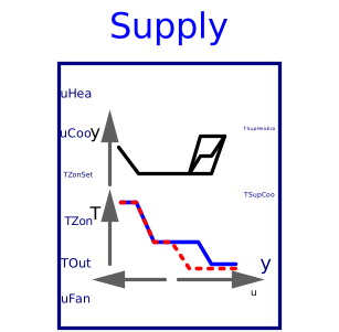
blockSupply
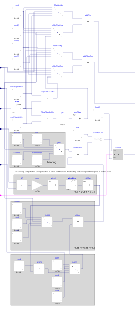
Information
Block that outputs the set points for the supply air temperature for cooling, heating and economizer control, and the fan speed for a single zone VAV system.
For the temperature set points, the
parameters are the maximum supply air temperature TSupSetMax,
and the minimum supply air temperature for cooling TSupSetMin.
The deadband temperature is equal to the
average set point for the zone temperature
for heating and cooling, as obtained from the input TZonSet,
constraint to be within 21°C (≈70 F) and
24°C (≈75 F).
The setpoints are computed as shown in the figure below.
Note that the setpoint for the supply air temperature for heating
and for economizer control is the same, and this setpoint is
lower than TSupSetMin when the heating loop signal
is zero and the economizer is in cooling mode, as shown in the figure.
For the fan speed set point, the
parameters are the maximu fan speed at heating yHeaMax,
the minimum fan speed yMin and
the maximum fan speed for cooling yCooMax.
For a cooling control signal of uCoo > 0.25,
the speed is faster increased the larger the difference is between
the zone temperature minus outdoor temperature TZon-TOut.
The figure below shows the sequence.

The output TSupCoo is to be used to control the cooling coil,
and the output
TSupHeaEco is to be used to control the heating coil and the
economizer dampers.
Note that the inputs uHea and uCoo must be computed
based on the same temperature sensors and control loops.
Parameters
| Type | Name | Default | Description |
|---|---|---|---|
| Temperatures | |||
| Real | TSupSetMax | Maximum supply air temperature for heating | |
| Real | TSupSetMin | Minimum supply air temperature for cooling | |
| Speed | |||
| Real | yHeaMax | Maximum fan speed for heating | |
| Real | yMin | Minimum fan speed | |
| Real | yCooMax | 1 | Maximum fan speed for cooling |
Connectors
| Type | Name | Default | Description |
|---|---|---|---|
| Buildings.Controls.OBC.CDL.Interfaces.RealInput | uHea | Heating control signal | |
| Buildings.Controls.OBC.CDL.Interfaces.RealInput | uCoo | Cooling control signal | |
| Buildings.Controls.OBC.CDL.Interfaces.RealInput | TZonSet | Average of heating and cooling setpoints for zone temperature | |
| Buildings.Controls.OBC.CDL.Interfaces.RealInput | TZon | Zone temperature | |
| Buildings.Controls.OBC.CDL.Interfaces.RealInput | TOut | Outdoor air temperature | |
| Buildings.Controls.OBC.CDL.Interfaces.RealOutput | TSupHeaEco | Temperature setpoint for heating coil and for economizer | |
| Buildings.Controls.OBC.CDL.Interfaces.RealOutput | TSupCoo | Cooling supply air temperature setpoint | |
| Buildings.Controls.OBC.CDL.Interfaces.RealOutput | y | Fan speed | |
| Buildings.Controls.OBC.CDL.Interfaces.BooleanInput | uFan | Supply fan status |
Components
| Type | Name | Default | Description |
|---|---|---|---|
| Buildings.Controls.OBC.CDL.Reals.Switch | switch | Switch to assign control signal | |
| Buildings.Controls.OBC.CDL.Reals.Sources.Constant | fanOff | Fan off status | |
| Buildings.Controls.OBC.CDL.Reals.Min | yFanHeaCoo | Fan speed due to heating or cooling |
Revisions
-
April 30, 2021, by Michael Wetter:
Added limiter to fan signal.
This is for issue 2475. -
August 1, 2019, by Kun Zhang:
Added a switch for fan control. -
March 21, 2019, by Jianjun Hu:
Used line block to avoid use of block that is not in CDL. This is for issue 1389. -
March 25, 2018, by Michael Wetter:
Revised implementation of fan speed control signal calculation to remove the hysteresis blocks.
This is for issue 1153. -
April 26, 2017, by Michael Wetter:
Updated documentation and renamed output signal toTSupHeaEco. -
January 10, 2017, by Michael Wetter:
First implementation.