
modelFans
Validation model for fans components
Extends from Modelica.Icons.Example (Icon for runnable examples).
Information
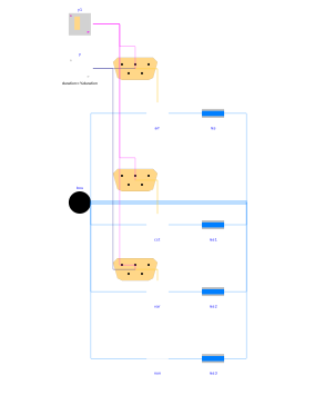
This model validates the models within Buildings.Templates.Components.Fans by exposing them to a control signal varying from 0 to 1 and connecting them to an air loop with a fixed flow resistance, which is sized based on the nominal operating point of the fan model.
Parameters
| Type | Name | Default | Description |
|---|---|---|---|
| Dynamics › Conservation equations | |||
| Modelica.Fluid.Types.Dynamics | energyDynamics | Modelica.Fluid.Types.Dynamics.FixedInitial | Type of energy balance: dynamic (3 initialization options) or steady state |
Connectors
| Type | Name | Default | Description |
|---|---|---|---|
| Interfaces.Bus | bus | Control bus | |
| Interfaces.Bus | bus1 | Control bus | |
| Interfaces.Bus | bus2 | Control bus |
Components
| Type | Name | Default | Description |
|---|---|---|---|
| Fluid.Sources.Boundary_pT | bou | Boundary conditions | |
| Buildings.Templates.Components.Fans.ArrayVariable | arr | Fan array | |
| Fluid.FixedResistances.PressureDrop | res | Ducts and coils equivalent flow resistance | |
| Buildings.Controls.OBC.CDL.Reals.Sources.Ramp | y | Fan control signal | |
| Buildings.Controls.OBC.CDL.Logical.Sources.TimeTable | y1 | Fan start/stop signal | |
| Buildings.Templates.Components.Fans.SingleVariable | var | Variable speed fan | |
| Buildings.Templates.Components.Fans.SingleConstant | cst | Constant speed fan | |
| Fluid.FixedResistances.PressureDrop | res1 | Ducts and coils equivalent flow resistance | |
| Fluid.FixedResistances.PressureDrop | res2 | Ducts and coils equivalent flow resistance | |
| Buildings.Templates.Components.Fans.None | non | No fan | |
| Fluid.FixedResistances.PressureDrop | res3 | Ducts and coils equivalent flow resistance |
Contents
| Name | Description |
|---|---|
 MediumAir MediumAir |