
modelRadiantHeatingCooling_TRoom
Extends from Buildings.ThermalZones.EnergyPlus_24_2_0.Examples.SingleFamilyHouse.Unconditioned (Example model with one unconditoned zone simulated in Modelica, and the other two unconditioned zones simulated in EnergyPlus).
Information
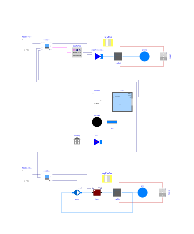
Model that uses EnergyPlus for the simulation of a building with one thermal zone that has a radiant ceiling, used for cooling, and a radiant floor, used for heating. The EnergyPlus model has one conditioned zone that is above ground. This conditioned zone has an unconditioned attic. The model is constructed by extending Buildings.ThermalZones.EnergyPlus_24_2_0.Examples.SingleFamilyHouse.Unconditioned and adding a radiant ceiling for cooling and an idealized heater for heating.
The next section explains how the radiant ceiling is configured.
Coupling of radiant ceiling to EnergyPlus model
The radiant ceiling is modeled in the instance slaCei at the top of the schematic model view,
using the model
Buildings.Fluid.HeatExchangers.RadiantSlabs.ParallelCircuitsSlab.
This instance models the heat transfer from the surface of the attic floor to the ceiling of the living room.
In this example, the construction is defined by the instance layCei.
(See the
Buildings.Fluid.HeatExchangers.RadiantSlabs.UsersGuide
for how to configure a radiant slab.)
In this example, the surfaces slaCei.surf_a (upward-facing) and
slaCei.surf_a (downward-facing)
are connected to the instance attFlo.
Because attFlo models the floor of the attic, rather than the ceiling
of the living room,
the heat port slaCei.surf_a is connected to attFlo.heaPorFro, which is the
front-facing surface, e.g., the floor.
Similarly, slaCei.surf_b is connected to attFlo.heaPorBac, which is the
back-facing surface, e.g., the ceiling of the living room.
The mass flow rate of the slab is constant if the cooling is operating. A P controller computes the control signal to track a set point for the room temperature. The controller uses a hysteresis to switch the mass flow rate on or off. The control signal is also used to set the set point for the water supply temperature to the slab. This temperature is limited by the dew point of the zone air to avoid condensation.
See also the model Buildings.ThermalZones.EnergyPlus_24_2_0.Examples.SingleFamilyHouse.RadiantHeatingCooling_TSurface which is controlled to track a set point for the surface temperature.
Coupling of radiant floor to EnergyPlus model
The radiant floor is modeled in the instance slaFlo at the bottom of the schematic model view,
using the model
Buildings.Fluid.HeatExchangers.RadiantSlabs.ParallelCircuitsSlab.
This instance models the heat transfer from surface of the floor to the lower surface of the slab.
In this example, the construction is defined by the instance layFloSoi.
(See the
Buildings.Fluid.HeatExchangers.RadiantSlabs.UsersGuide
for how to configure a radiant slab.)
In this example, the surfaces slaFlo.surf_a and
slaFlo.surf_b
are connected to the instance
flo.
In EnergyPlus, the surface flo.heaPorBac is connected
to the boundary condition of the soil because this building has no basement.
Note that the floor construction is modeled with 2 m of soil because the soil temperature in EnergyPlus is assumed to be undisturbed.
Parameters
| Type | Name | Default | Description |
|---|---|---|---|
| Modelica.Units.SI.Volume | VRoo (from Unconditioned) | 453.1 | Room volume |
| Modelica.Units.SI.MassFlowRate | m_flow_nominal (from Unconditioned) | VRoo*1.2*0.3/3600 | Nominal mass flow rate |
| Modelica.Units.SI.Area | AFlo | 185.8 | Floor area |
| Modelica.Units.SI.HeatFlowRate | QHea_flow_nominal | 8000 | Nominal heat flow rate for heating |
| Modelica.Units.SI.MassFlowRate | mHea_flow_nominal | QHea_flow_nominal/4200/10 | Design water mass flow rate for heating |
| Modelica.Units.SI.HeatFlowRate | QCoo_flow_nominal | -3000 | Nominal heat flow rate for cooling |
| Modelica.Units.SI.MassFlowRate | mCoo_flow_nominal | -QCoo_flow_nominal/4200/5 | Design water mass flow rate for heating |
| Buildings.HeatTransfer.Data.OpaqueConstructions.Generic | layFloSoi | Material layers from surface a to b (8cm concrete, 20 cm insulation, 20 cm concrete, 200 cm soil, below which is the undisturbed soil assumed) | |
| Buildings.HeatTransfer.Data.OpaqueConstructions.Generic | layCei | Material layers from surface a to b (8cm concrete, 10 cm insulation, 18+2 cm concrete) |
Components
Contents
| Name | Description |
|---|---|
 MediumW MediumW | Water medium |
Revisions
-
March 13, 2024, by Michael Wetter:
Updatedidffile to add insulation, and resized system.
This is for issue 3707. -
December 1, 2022, by Michael Wetter:
Increased thickness of insulation of radiant slab and changed pipe spacing. -
March 30, 2021, by Michael Wetter:
First implementation.