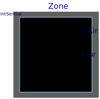
modelZone
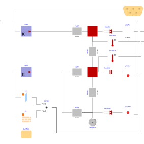
Information
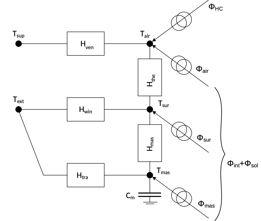
This is a lumped-capacity simplified building model based on the 5R1C
network presented in the ISO 13790:2008 Standard. The simplified 5R1C model uses
five thermal resistances and one thermal capacity to reproduce the
transient thermal behaviour of buildings. The thermal zone is modeled with three
temperature nodes, the indoor air temperature TAir, the envelope internal
surface temperature TSur and the zone's mass temperature TMas
(the heat port is not shown in the figure), and two boundary
condition nodes, supply air temperature TSup and the external air temperature
TExt. The five resistances are related to heat transfer by ventilation HVen,
windows HWin, opaque components (split between HTra and HMas) and heat
transfer between the internal surfaces of walls and the air temperature HThe.
The thermal capacity Cm includes the thermal capacity of the entire zone. The heating and/or
cooling demand is found by calculating the heating and/or cooling power ΦHC that
needs to be supplied to, or extracted from, the internal air node to maintain a
certain set-point. Internal, Φint , and solar, Φsol, heat gains are input values,
which are split in three components.
The ventilation heat transfer coefficient Hven is calculated using
Hven = ρa ca ∑kV̇k,
where ρa is the density of air, ca is the specific heat capacity of air and V̇k is the k-th volumetric external air flow rate. The coupling conductance Hthe is given byHthe = has Atot,
where has is the heat transfer coefficient between the air node the surface node, with a fixed value of 3.45 W/m2K, and Atot is the area of all surfaces facing the building zone. The thermal transmission coefficient of windows Hwin is calculated usingHwin = ∑kUwin,kAwin,k,
where Uwin,k is the thermal transmittance of window element k of the building envelope and Ak is the area of the window element k of the building envelope. The coupling conductance Hmas is given byHmas =hms fms Af,
where hms is the heat transfer coefficient between the mass node and the surface node, with fixed value of 9.1 W/m2K, fms is a correction factor, and Af is the floor area. The correction factor fms can be assumed as 2.5 for light and medium building constructions, and 3 for heavy constructions. The coupling conductance Htra is calculated usingHtra = 1 ⁄ (1 ⁄ Hop - 1 ⁄ Hmas),
where Hop is the thermal transmission coefficient of opaque elements. The three heat gains components are calculated usingΦair = 0.5 Φint,
Φsur = (1-fms Af ⁄ Atot -Hwin ⁄ hms Atot)(0.5 Φint+ Φsol),
Φmas = fms Af ⁄ Atot (0.5Φint + Φsol).
Tips for parametrization
-
The parameters
AWin,AWal,surTilandsurAzimust have the same dimension ofnOrientations. -
The areas in
AWalmust account only for the opaque parts of the walls (excluding windows). The floor and roof area is entered throughAFloandARooand must not be entered as part ofAWal. - If a wall contains only opaque parts, the corresponding window area must be set to 0.
-
The parameter
coeFacis used to vary the g-factor as a function of the incident angle of the surface. Often, the curve can be approximated by a cubic polynomial, as shown in Buildings.ThermalZones.ISO13790.Validation.BESTEST.Case600. When this information is not available, the parametercoeFacmust be set to 1.
Parameters
| Type | Name | Default | Description |
|---|---|---|---|
| Modelica.Units.SI.Area | AFlo | Net conditioned floor area | |
| Modelica.Units.SI.Volume | VRoo | Volume of room | |
| Modelica.Units.SI.CoefficientOfHeatTransfer | hInt | 3.45 | Heat transfer coefficient between surface and air nodes |
| ISO13790.Data.Generic | buiMas | Building mass | |
| Integer | nOrientations | 4 | Number of orientations for vertical walls |
| Modelica.Units.SI.Angle[nOrientations] | surTil | Tilt angle of surfaces | |
| Modelica.Units.SI.Angle[nOrientations] | surAzi | Azimuth angle of surfaces | |
| Ventilation | |||
| Real | airRat | Air change rate | |
| Windows | |||
| Modelica.Units.SI.Area[nOrientations] | AWin | Area of windows | |
| Modelica.Units.SI.CoefficientOfHeatTransfer | UWin | U-value of windows | |
| Real | winFra | 0.001 | Frame fraction of windows |
| Real | gFac | Energy transmittance of glazings | |
| Real[:] | coeFac | {1} | Polynomial coefficients for gFac |
| Real | shaRedFac | 1 | Shading reduction factor |
| Opaque constructions | |||
| Modelica.Units.SI.Area[nOrientations] | AWal | Area of external walls (only opaque part) | |
| Modelica.Units.SI.Area | ARoo | Area of roof | |
| Modelica.Units.SI.CoefficientOfHeatTransfer | UWal | U-value of external walls | |
| Modelica.Units.SI.CoefficientOfHeatTransfer | URoo | U-value of roof | |
| Modelica.Units.SI.CoefficientOfHeatTransfer | UFlo | U-value of floor | |
| Real | b | 0.5 | Adjustment factor for ground heat transfer |
Connectors
| Type | Name | Default | Description |
|---|---|---|---|
| Modelica.Blocks.Interfaces.RealInput | intSenGai | Internal sensible heat gains | |
| Modelica.Blocks.Interfaces.RealOutput | TAir | Room air temperature | |
| Modelica.Blocks.Interfaces.RealOutput | TSur | Average inside surface temperature | |
| Buildings.BoundaryConditions.WeatherData.Bus | weaBus | Weather data bus | |
| Modelica.Thermal.HeatTransfer.Interfaces.HeatPort_a | heaPorAir | Heat port to air node | |
| Modelica.Thermal.HeatTransfer.Interfaces.HeatPort_a | heaPorSur | Heat port to surface temperatures |
Components
Revisions
-
May 8, 2024, by Michael Wetter:
Removed connection to itself. -
Mar 16, 2022, by Alessandro Maccarini:
First implementation.