
modelSoftwareReleaseProject
Extends from BusinessSimulation.Icons.Example (Icon for an example).
Information
This information is part of the Business Simulation Library (BSL). Please support this work and ► donate.
In 2007 Erik J.A. van Zijderveld introduced what he coined a "Method to Analyse Relations between Variables using Enriched Loops (MARVEL)" [24]. He made the following observations:
- A causal loop diagram (CLD)—or impact diagram—is a good tool for integrating information from different stakeholdes and a modeling paradigm, which people with different backgrounds can easily relate to.
- While quantitative data may be hard to obtain quickly and reliably, stakeholders and decision makers can often reach consensus on speed and strength with regard to impact relations.
- Decision makers can typically identify pressure or intervention points and relevant performance indicators in such diagrams.
- Often to come up with relevant insight it will suffice to show initial dynamic behavior, i.e., we do not need the kind of long-run validity that a fully fledged simulation model provides—given that the effort building such a model will usually be 10 to 100 times higher.
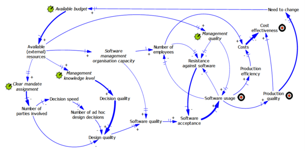 |
In the diagram, the thickness of an arrow indicates the strengh of impact whereas length and number of "barriers" at their tips indicate the speed of impact propagation. These attributes are assigned qualitatively using weak, average, strong, very strong to rank strengths and low, average, high, very high to rank speeds.
The model diagram below illustrates how such a model can be built using the →CausalLoop package. Impact relations between variables are encoded using the →ProportionalityDelayed component with global parameters for strength (wk, av, st, vs) and speed (v1, v2, v3, v4) in place, the latter being transformed to delay times, which are inversely related to speed.
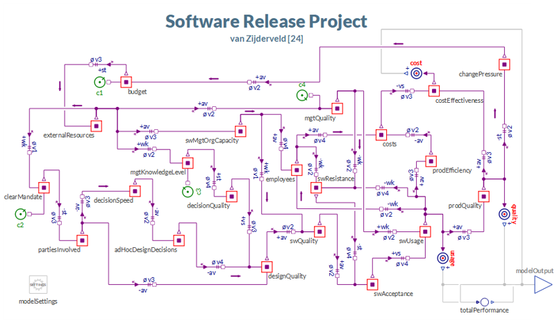 |
In accordance with the MARVEL version there are four control or intervention points, which can be turned on or off for a simulation run:
c1: budget control withsetpoint = 0.8c2: mandate control withsetpoint = 0.7c3: management knowledge level control withsetpoint = 0.5c4: management quality control withsetpoint = 0.6
These controls mean that whenever there is a deviation between setpoint and actual level of the variable under control, then corrective action will be taken, i.e. a flow to the stock, in order to erradicate the deviation within the chosen adjustment time, whcih is set to 1 yr for all controls.
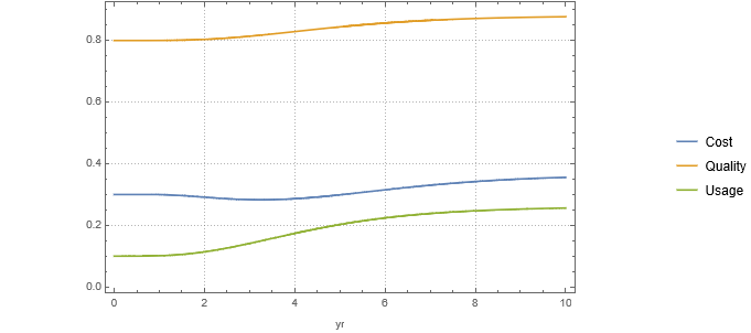
There are three main performance goals: cost effectiveness (costs), production quality (quality), and software usage (usage). In this example the normalized stock values pertaining to the goals are simply mapped upon the linear scale [0,1]. The graph blow shows the development for these performance indicators over a period of 10 years with just the budget control (c1) activated.
 |
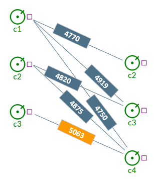
In order to better combare different scenarios we can use a weighted average performance and calculate the mean over the simulation period (→totalPerformance). Using this measure we can compare different combinations of interventions and it turns out that a combination of c3 and c4 shows best average performance albeit withouth considering the control effort (see Notes).
 |
Notes
- The parameters in the model are set to the values specified in van Zijderveld's paper whenever possible.
- The model by specification is set up in equilibrium as there are not processes of exogenous growth in the model and all motion is triggered by changes. If at least one control is activated the model will show dynamic behavior.
- Since control elements (optionally) report their rates, i.e., the control effort, one can readily expand the evaluation of scenarios by comparing performance gains to the required control effort.
See also
Parameters
| Type | Name | Default | Description |
|---|---|---|---|
| Performance | |||
| Ratio | wCost | 1 | Weigth for cost performance |
| Ratio | wQuality | 1 | Weigth for quality performance |
| Ratio | wUsage | 1 | Weigth for usage performance |
| Strength of Influence | |||
| Ratio | wk | 0.2 | Weak influence |
| Ratio | av | 0.5 | Average influence |
| Ratio | st | 1 | Strong influence |
| Ratio | vs | 1.2 | Very strong influence |
| Speed of Influence | |||
| Time | v4 | 0.25 | Very high speed |
| Time | v3 | 0.5 | High speed |
| Time | v2 | 1 | Average speed |
| Time | v1 | 3 | Low speed |
Connectors
| Type | Name | Default | Description |
|---|---|---|---|
| Interfaces.Connectors.DataOutPort | modelOutput | The model's performance output |
Components
| Type | Name | Default | Description |
|---|---|---|---|
| Theta | theta | ||
| ModelSettings | modelSettings |
Contents
| Name | Description |
|---|---|
 Theta Theta | Structural parameters |
 AccumulatedPerformance AccumulatedPerformance | Weighted average performance per period |
Revisions
- Added in v2.0.0.