modelSM_3ph
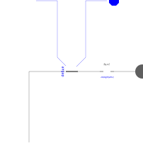
Extends from ComplexLib.Machines.Interfaces.PartialBasicElectricMachine3ph_wBalance (Basic model for three-phase electric machines (using current phasor balance, but no power calculation)).
Information
This approximation of a three-phase synchronous machine using phasor
domain for the electrical subsystem is based on the behaviour of the
steady-state equivalent circuit of such a machine.
This behaviour is defined by appropriate equations.
The machine is an extension of the partial Interface package model
PartialBasicElectricMachine3ph_wBalance of an electric
three-phase machine including the current balances.
The model has two electrical connectors of type ComplexPlug (which correspond
to six connectors of type ComplexPin) and one mechanical rotational flange.
The stator is assumed to be fixed in the housing.
The electrical submodel has three phases if the default value of the
'number of phases'-parameter m is used.
In order to model a system with different number of phases, the
'number of phases'-parameter has to be changed in all
appearing multi-phase components and connectors.
Each phase consists of a constant inductance (stator's self-inductance)
and an electromagnetic force (emf) realising the effect of the rotor current
on the stator via the mutual inductance.
All inductances are assumed to be ideal (electrically linear, no
saturation).
The mechanical submodel contains a shaft which is fixed to the rotor.
Using this model, one can carry out steady-state or quasi-stationary
investigations of the electrical subsystem.
The mechanical subsystem may show transient behaviour which must be
sufficiently slow.
Attention!!!
To ensure that the phasor domain-based model works in a quasi-stationary
mode, the torque angle δ (also called rotor displacement angle)
may alter only very slowly in comparison with both the nominal frequency
f=ω/(2π) and the dominant time constant of the electrical
subsystem.
Fraunhofer IIS/EAS, Dresden
email: olaf.enge@eas.iis.fraunhofer.de
Parameters
| Type | Name | Default | Description |
|---|---|---|---|
| Modelica.SIunits.Inertia | J_Rotor (from PartialBasicMachine) | 1 | Rotor's moment of inertia |
| Integer | m (from PartialBasicElectricMachine3ph_wBalance) | 3 | Number of phases |
| Integer | p | 1 | Number of poles |
| SI.Inductance | Ls | 0.01 | Stator inductance per phase |
| SI.Inductance | Lm | 0.009 | Mutual inductance per phase |
| SI.Voltage | Vr | 1 | Dc voltage at rotor |
| SI.Resistance | Rr | 1 | Rotor resistance |
| Real | eps | 1e-12 | To avoid division by zero |
| Integer | k | 1 | Phase index |
Connectors
| Type | Name | Default | Description |
|---|---|---|---|
| Modelica.Mechanics.Rotational.Interfaces.Flange_a | shaft (from PartialBasicMachine) | Flange at shaft | |
| ComplexLib.MultiPhase.Interfaces.PosComplexPlug | plug_p (from PartialBasicElectricMachine3ph_wBalance) | Positive complex plug | |
| ComplexLib.MultiPhase.Interfaces.NegComplexPlug | plug_n (from PartialBasicElectricMachine3ph_wBalance) | Negative complex plug | |
| Modelica.Blocks.Interfaces.RealOutput | Trq_electrical | Electrically produced torque |
Components
| Type | Name | Default | Description |
|---|---|---|---|
| Modelica.Mechanics.Rotational.Components.Inertia | inertiaRotor (from PartialBasicMachine) | ||
| Modelica.Mechanics.Rotational.Components.Fixed | fixedHousing (from PartialBasicMachine) | ||
| SI.Voltage[m] | v (from PartialBasicElectricMachine3ph_wBalance) | Voltages between the two plugs | |
| SI.Voltage[m] | vRe (from PartialBasicElectricMachine3ph_wBalance) | Active parts of voltage phasors | |
| SI.Voltage[m] | vIm (from PartialBasicElectricMachine3ph_wBalance) | Reactive parts of voltage phasors | |
| SI.Current[m] | i (from PartialBasicElectricMachine3ph_wBalance) | Currents flowing into positive plug | |
| SI.Current[m] | iRe (from PartialBasicElectricMachine3ph_wBalance) | Active parts of current phasors | |
| SI.Current[m] | iIm (from PartialBasicElectricMachine3ph_wBalance) | Reactive parts of current phasors | |
| SI.Current | Ir | Rotor current | |
| SI.Voltage | Ef | Mutual voltage source, depending on rotor current and angular difference between shaft and field | |
| SI.AngularFrequency | omegaN | Angular frequency of net voltage | |
| SI.AngularFrequency | omegaField | Angular frequency of field | |
| SI.AngularFrequency | omegaMech | Angular velocity of rotor | |
| Real | vSum | Sum of rms values of voltages of all phases | |
| SI.Torque | Tp | Pull-out (maximum) torque | |
| SI.Angle | gamma | Angular difference between shaft and field | |
| SI.Angle | delta | Torque angle | |
| SI.Torque | Trq | Torque produced electrically | |
| SI.Power | P_mech | Mechanical power | |
| SI.Resistance | Xs | Stator (or synchronous) reactance | |
| SI.Resistance | Xm | Main reactance | |
| SI.Angle | phase_Vs | Phase of first stator voltage | |
| SI.Angle | phase_Is | Phase of first stator current | |
| SI.Angle | phase_Ef | Phase of back-emf voltage | |
| SI.Angle | phase | Phase of stator voltage with respect to stator current | |
| SI.Angle | phiN | Angle of net voltage | |
| SI.Angle | phiField | Angle of rotating field | |
| SI.Angle | phiMech | Angle of shaft | |
| ComplexLib.Machines.Interfaces.AirGap | airgap |