modelVRNordic
Voltage regulator model for the Nordic 32 test system used for voltage stability studies
Information
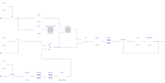
This model implements the AVR, PSS and overexcitation limiter of the generator frames in the Nordic 32 test system used for voltage stability studies.The overexcitation limiter uses a delayed activation with specifics depending on the generator.
Certain generators reduce the delay by assigning a linear function to the error signal of the excitation current and its limit, this is implemented in the overexcitation limitation model.
Parameters
| Type | Name | Default | Description |
|---|---|---|---|
| Types.VoltageModulePu | EfdMaxPu | Upper limit of excitation voltage in pu (user-selected base voltage) | |
| Real | OelMode | For positive field current error signal : if 1, OEL output constant, if 0, OEL output equal to error signal | |
| Types.CurrentModulePu | IrLimPu | Rotor current limit in pu (base SNom, UNom) | |
| Types.PerUnit | KPss | Gain of PSS | |
| Types.PerUnit | KTgr | Gain of transient gain reduction | |
| Types.Time | tDerOmega | Derivative time constant of first PSS filter for angular frequency, in s | |
| Types.Time | tLagPss | Lag time constant of second and third PSS filters in s | |
| Types.Time | tLagTgr | Lag time constant of transient gain reduction in s | |
| Types.Time | tLeadPss | Lead time constant of second and third PSS filters in s | |
| Types.Time | tLeadTgr | Lead time constant of transient gain reduction in s | |
| Types.Time | tOelMin | Lower limit of OEL timer in s | |
| Types.VoltageModulePu | Efd0Pu | Initial excitation voltage in pu (user-selected base voltage) | |
| Types.CurrentModulePu | Ir0Pu | Initial rotor current in pu (base SNom, UNom) | |
| Types.VoltageModulePu | Us0Pu | Initial stator voltage in pu (base UNom) | |
| Types.VoltageModule | UsRef0Pu | Efd0Pu/KTgr + Us0Pu | Reference stator voltage in pu (base UNom) |
Connectors
| Type | Name | Default | Description |
|---|---|---|---|
| Modelica.Blocks.Interfaces.RealInput | IrPu | Rotor current in pu (base SNom, UNom) | |
| Modelica.Blocks.Interfaces.RealInput | omegaPu | Angular frequency in pu (base omegaNom) | |
| Modelica.Blocks.Interfaces.RealInput | UsPu | Stator voltage in pu (base UNom) | |
| Modelica.Blocks.Interfaces.RealOutput | efdPu | Excitation voltage in pu (user-selected base voltage) | |
| Dynawo.Connectors.ImPin | efdPuPin | Pin for connecting efdPu to the generator |