modelIdealSwitch
Ideal switch

Extends from AdditionalIcons.Switch, Dynawo.Electrical.Controls.Basics.SwitchOff.SwitchOffIdealSwitch (Switch-off signal for an ideal switch).
Information
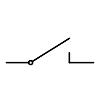
When the switch is closed, the voltage on both terminals ar equal and the current is going through the switch.When the switch is open, the current going through the switch is zero.
The equivalent circuit and conventions is:
I1 I2
(terminal1) -->-------/ -------<-- (terminal2)
Parameters
| Type | Name | Default | Description |
|---|---|---|---|
| Integer | NbSwitchOffSignals (from SwitchOffLogic) | Number of switch-off signals to take into account in inputs | |
| Boolean | SwitchOffSignal10 (from SwitchOffLogic) | false | Initial switch-off signal 1 |
| Boolean | SwitchOffSignal20 (from SwitchOffLogic) | false | Initial switch-off signal 2 |
| Boolean | SwitchOffSignal30 (from SwitchOffLogic) | false | Initial switch-off signal 3 |
| Boolean | Running0 (from SwitchOffLogic) | if NbSwitchOffSignals >= 3 then not (SwitchOffSignal10 or SwitchOffSignal20 or SwitchOffSignal30) elseif NbSwitchOffSignals >= 2 then not (SwitchOffSignal10 or SwitchOffSignal20) else not SwitchOffSignal10 | Indicates if the component is initially running or not |
| Constants.state | State0 (from SwitchOffIdealSwitch) | Constants.state.Closed | Start value of connection state |
Connectors
| Type | Name | Default | Description |
|---|---|---|---|
| Dynawo.Connectors.BPin | switchOffSignal1 (from SwitchOffLogic) | Switch-off signal 1 | |
| Dynawo.Connectors.BPin | switchOffSignal2 (from SwitchOffLogic) | Switch-off signal 2 | |
| Dynawo.Connectors.BPin | switchOffSignal3 (from SwitchOffLogic) | Switch-off signal 3 | |
| Dynawo.Connectors.BPin | running (from SwitchOffLogic) | Indicates if the component is running or not | |
| Dynawo.Connectors.ACPower | terminal1 | Switch side 1 | |
| Dynawo.Connectors.ACPower | terminal2 | Switch side 2 |
Components
| Type | Name | Default | Description |
|---|---|---|---|
| Constants.state | state (from SwitchOffIdealSwitch) | Ideal switch connection state | |
| Types.ActivePowerPu | P1Pu | Active power on side 1 in pu (base SnRef) (receptor convention) | |
| Types.ReactivePowerPu | Q1Pu | Reactive power on side 1 in pu (base SnRef) (receptor convention) | |
| Types.ActivePowerPu | P1GenPu | Active power on side 1 in pu (base SnRef) (generator convention) | |
| Types.ReactivePowerPu | Q1GenPu | Reactive power on side 1 in pu (base SnRef) (generator convention) | |
| Types.ActivePowerPu | P2Pu | Active power on side 2 in pu (base SnRef) (receptor convention) | |
| Types.ReactivePowerPu | Q2Pu | Reactive power on side 2 in pu (base SnRef) (receptor convention) |