This example and the data are inspired by the article [P.
Pourbeik and J. K.
Petter,
“Modeling and
validation ofbatteryenergystoragesystems using simple genericmodels for power system stabilitystudies”, CIGRE Science and Engineering,
October 2017, pp.
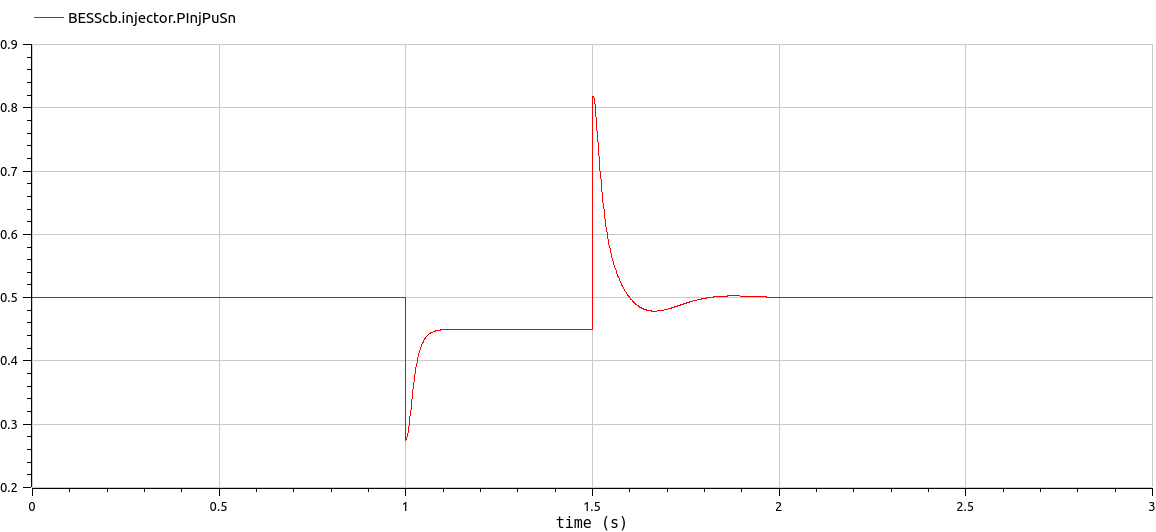
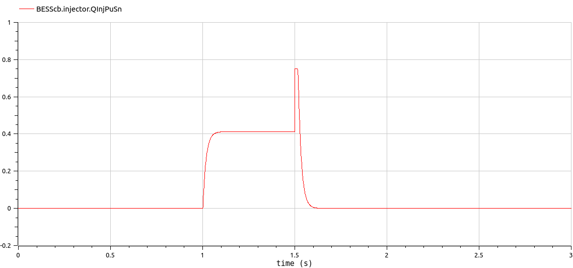
63-72.]At initial time, the active power demanded by the battery
is 0.5 pu (base SNom = 6MVA) and the reactive power is 0 pu (base
SNom = 6MVA).The BESS is able to discharge since the initial state of
charge SOC0Pu = 0.5 is between the accepted range [SOCMinPu = 0.2 ,
SOCMaxPu = 0.8]. Since the simulation is only for 3 s, and the
discharge time is considered much longer, the state of charge SOCPu
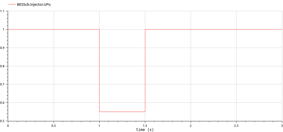
is considered constant all along the simulation time.At t = 1 s, a fault at the infinite bus is simulated and it
can be seen that the BESS starts injecting reactive power until the
fault is cleared at t = 1.5 s.
Generated at 2026-07-12T20:48:41Z by OpenModelicaOpenModelica 1.27.0 using
GenerateDoc.mos