In this example, two inertial grids are connected together and with
a load. It allows to make appearing an interarea oscillation. The
frequency of this oscillation can be theoretically calculated using
a few approximations (U1 = U2 = 1 for example). It leads to find a
mode in the system at the following frequency: f =
sqrt(omega0/HX)/2*Pi.
The theoretical derivations are provided in the following
paper:
C. Cardozo et al., "Small Signal Stability Analysis of the
Angle Difference Control on a HVDC Interconnection Embedded in the
CE Synchronous Power System," 2020 IEEE/PES Transmission and
Distribution Conference and Exposition (T&D), Chicago, IL, USA,
2020, pp. 1-5, doi: 10.1109/TD39804.2020.9300036.
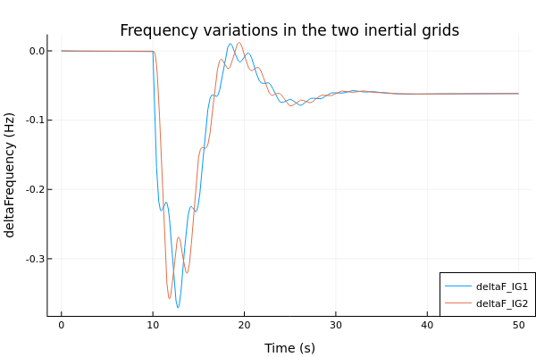
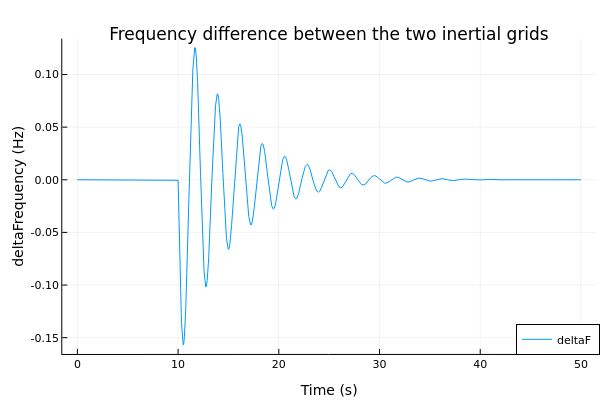
It means that the frequency of the interarea oscillation can
be easily moved in a range of frequency. With the particular values
provided in this case we obtained a mode at f = 0.45 Hz, as
demonstrated by the plots below.
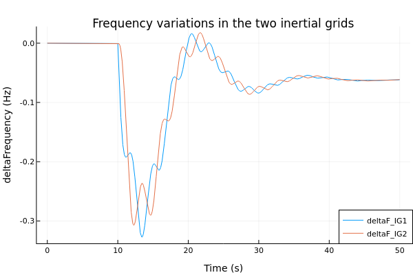
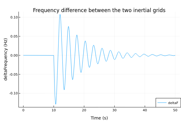
By taking H = 4 for example, we end up with a different mode
(f = 0.36 Hz), as visible in the plot below.
The test case can be used and modified to assess the
contribution of any device under test to the interarea mode.