Description of concepts
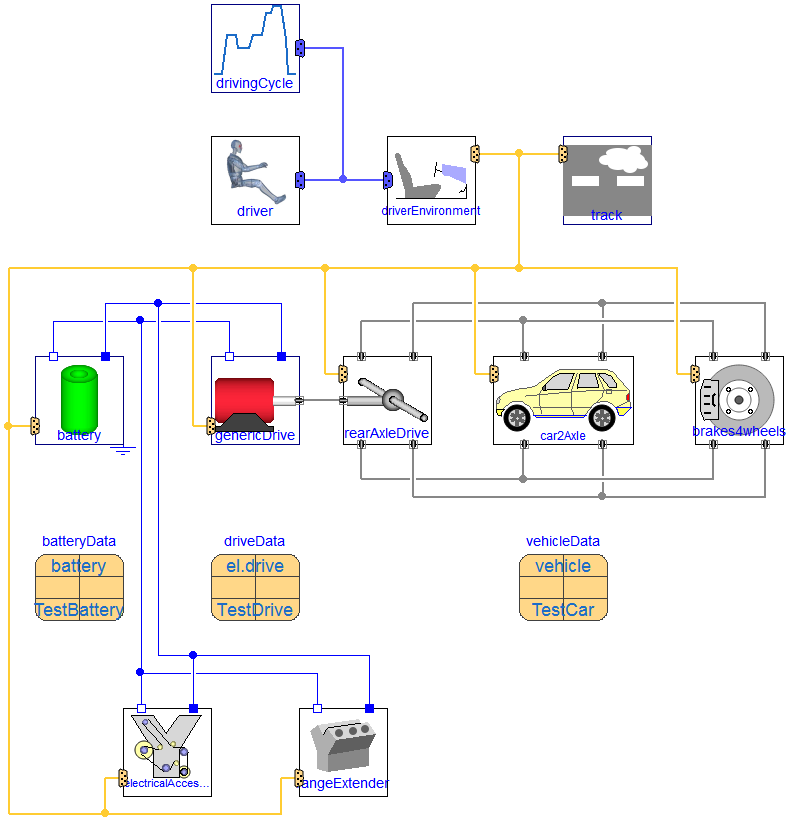
Vehicle structure
- chassis model with
dynamic behaviour of the vehicle mass, four wheels with inertia and
driving resistances (inclination, rolling resistance and drag)
- brake system
- drive line model to
distribute the motor torque to the wheels in a flexible way
- electric drive
model with electric machine, current/torque control and power
convrter to connect to the dc source/battery
- battery
model
- track model defining
inclination and rollng resistance coefficient along the track as
well as wind speed
- driver
environment maps signals between the control bus and the driver
interface (see below)
The throttle and brake signals are provided either
The sign of the throttle signal depends on direction of movement
(forward/backward), the brake signal is in the range of [0..1]. The
driverEnvironment.recuperationController
decides about mechanical braking or recuperation, sending the
appropriate signals to the brakes and motor bus.
You may add:
Control bus
As defined in the Vehicle
Interface library, there is a common control bus summarizing
sub-busses of the sub-systems to enable the communication between
all components. The driver environment
maps driver information and control bus signals in both
directions.
Parameterization
Parameter definition can be done by parameter records:
Thermal management
All components except the chassis have optional thermal
connectors to be able to control the distribution of loss power.
The losses at the chassis (drag and rolling resistance) are located
at the surface of the vehicle and are supposed not to be part of
the thermal management.
Generated at 2026-07-12T20:48:41Z by OpenModelicaOpenModelica 1.27.0 using
GenerateDoc.mos