
modelHeatPump_ConsoClim
Information
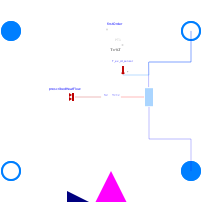
This model is used to determine the performances of a heat pump for different operating conditions. The ConsoClim model developed by the MINES PARISTECH is used.
The model predicts the performances of the system with three polynomial laws. The parameters of the model are identified with manufacturer data.
The first and the second law (EIRFT and CAPFT) are used respectively to determine the COP and the heating capacity of the machine at full load. These two polynomial laws depend on the outside air temperature (T_a_out) and the temperature of the water at the exhaust of the condenser (T_w). The third law is used to determine the performances of the system at part load.
The primary side fluid is modeled by means of 1-D incompressible fluid flow model (Cell1DimInc), in which a dynamic energy balance and static mass and momentum balances are applied on the fluid. The heat transfer in the primary fluid is modeled with a constant heat transfer coefficient. However, it can be changed to other heat transfer models through the HeatTransfer parameter in the fluid model.
Furthermore, the model includes a Boolean input connector on_off, which defines the operational state of the heat pump. In the equations, the Boolean input is translated to a variable value together with a first order block, which can take into account a start-up time constraint. The model also includes a real input connector W_dot_set to define the power that is injected to the heat pump. This connector is useful, for example, in the case where a heat pump is powered by the CHP electrical generation.
Parameters
| Type | Name | Default | Description |
|---|---|---|---|
| Modelica.Units.SI.Volume | V | 0.005 | Internal volume |
| Modelica.Units.SI.Area | A | 10 | Heat exchange area |
| Real | COP_n | 3.9505 | Nominal coefficient of performance |
| Modelica.Units.SI.HeatFlowRate | Q_dot_cd_n | 10.02 | Nominal thermal power at the condenser |
| Modelica.Units.SI.Temperature | T_su_ev_n | 7 | Nominal supply temperature at the evaporator |
| Modelica.Units.SI.Temperature | T_ex_cd_n | 35 | Nominal exhaust temperature at the condenser |
| Real | C0 | 0.949 | |
| Real | C1 | -8.05 | |
| Real | C2 | 111.09 | |
| Real | D0 | 0.968 | |
| Real | D1 | 0.0226 | |
| Real | D2 | -0.0063 | |
| Real | K1 | 0 | |
| Real | K2 | 0.67 | |
| Real | a | 0.7701 | |
| Real | b | 0.2299 | |
| Boolean | Variable_Compressor_Speed | false | Set false if the compressor speed is constant |
| Modelica.Units.SI.Temperature | Tmax | 273.15 + 100 | Maximum temperature at the outlet |
| Modelica.Units.SI.Time | tau | 60 | Start-up time constant |
| Initialization | |||
| Modelica.Units.SI.Temperature | Th_start | 35 + 273.15 | Start value for the condenser temperature |
Connectors
| Type | Name | Default | Description |
|---|---|---|---|
| Modelica.Fluid.Interfaces.FluidPort_a | Supply_cd | ||
| Modelica.Fluid.Interfaces.FluidPort_b | Exhaust_cd | ||
| Modelica.Fluid.Interfaces.FluidPort_a | Supply_ev | ||
| Modelica.Fluid.Interfaces.FluidPort_b | Exhaust_ev | ||
| Modelica.Blocks.Interfaces.RealInput | W_dot_set | ||
| Modelica.Blocks.Interfaces.BooleanInput | on_off |
Components
| Type | Name | Default | Description |
|---|---|---|---|
| Modelica.Units.SI.MassFlowRate | m_dot_ev | ||
| Modelica.Units.SI.SpecificEnthalpy | h_su_ev | ||
| Modelica.Units.SI.SpecificEnthalpy | h_ex_ev | ||
| Modelica.Units.SI.HeatFlowRate | Q_dot_cd | ||
| Modelica.Units.SI.HeatFlowRate | Q_dot_ev | ||
| Modelica.Units.SI.HeatFlowRate | Q_dot_cd_fl | ||
| Modelica.Units.SI.Temperature | T_su_ev | ||
| Modelica.Units.SI.Temperature | T_ex_cd | ||
| Modelica.Units.SI.InstantaneousPower | W_dot_n | ||
| Modelica.Units.SI.InstantaneousPower | W_dot_fl | ||
| Modelica.Units.SI.InstantaneousPower | W_dot_cp | ||
| Real | COP | ||
| Real | DELTA_T | ||
| Real | EIRFT | ||
| Real | COP_fl | ||
| Real | CAPFT | ||
| Real | PLR | ||
| Real | EIRFPLR | ||
| Real | PLR_30 | ||
| Real | EIRFPLR_30 | ||
| Real | COP_30 | ||
| Modelica.Units.SI.HeatFlowRate | Q_dot_30 | ||
| Modelica.Units.SI.InstantaneousPower | W_dot_30 | ||
| Flows.FluidFlow.Cell1DimInc | fluid | ||
| Interfaces.Heat.HeatPortConverter | heatPortConverter | ||
| Modelica.Thermal.HeatTransfer.Sources.PrescribedHeatFlow | prescribedHeatFlow | ||
| Modelica.Blocks.Continuous.FirstOrder | firstOrder | ||
| Modelica.Fluid.Sensors.Temperature | T_ex_cd_sensor |
Contents
| Name | Description |
|---|---|
 Medium1 | |
| Medium2 |