
modelBasic
Extends from Modelica.Icons.Example (Icon for runnable examples).
Information
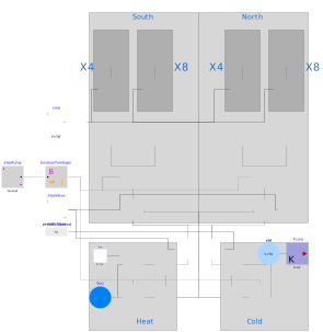
Example model demonstrating the use of the IBPSA components in a larger system.
This model is extended in
IBPSA.Fluid.Examples.FlowSystem.Simplified1,
IBPSA.Fluid.Examples.FlowSystem.Simplified2,
IBPSA.Fluid.Examples.FlowSystem.Simplified3.
In these examples, the flow network is simplified in three steps, which reduces the size of algebraic loops.
The system model is for a hydronic system with a hot and cold water production device,
each having its own circulation pump.
The warm and cold supply water temperatures are selected by switching the bottom two-way valves.
The building consists of a west and east wing.
Each wing has multiple zones that are heated or cooled using the hydronic system.
Each wing has a north and south section with a different supply temperature,
which is controlled using two main three way valves.
In total there are therefore four supply pipes,
which are each connected to four or eight emission devices in the zones.
The flow through the emission devices is controlled using two way valves.
The emission device itself also generates a pressure drop,
represented by components tabsX.
Note that the emission devices are in the real building
cooling and heating concrete slabs, but this simplified example
only models their flow resistance.
The control model consists of dummy inputs.
Components
| Type | Name | Default | Description |
|---|---|---|---|
| IBPSA.Fluid.Movers.FlowControlled_dp | pmpSouth | Pump to south of building | |
| IBPSA.Fluid.FixedResistances.PressureDrop | pipSouth1 | Pipe 1 to south of building | |
| IBPSA.Fluid.FixedResistances.PressureDrop | pipSouth2 | Pipe 2 to south of building | |
| IBPSA.Fluid.Movers.FlowControlled_dp | pmpNorth | Pump to north of building | |
| IBPSA.Fluid.FixedResistances.PressureDrop | pipNorth2 | Pipe 2 to north of building | |
| IBPSA.Fluid.FixedResistances.PressureDrop | pipNorth1 | Pipe 1 to north of building | |
| IBPSA.Fluid.Actuators.Valves.TwoWayLinear | valSouth1 | Valves on souther tabs section 1 | |
| IBPSA.Fluid.Actuators.Valves.TwoWayLinear | valSouth2 | Valves on souther tabs section 2 | |
| IBPSA.Fluid.Actuators.Valves.TwoWayLinear | valNorth1 | Valves on northern tabs section 1 | |
| IBPSA.Fluid.Actuators.Valves.TwoWayLinear | valNorth2 | Valves on northern tabs section 2 | |
| Modelica.Blocks.Math.BooleanToInteger | booleanToInteger | Boolean to integer conversion block | |
| Modelica.Blocks.Sources.BooleanPulse | stepPump | Step control | |
| Modelica.Blocks.Sources.Sine | sine | Valve control signal | |
| IBPSA.Fluid.Actuators.Valves.ThreeWayLinear | valSouth | Three way valve for controlling supply temperature to south of building | |
| IBPSA.Fluid.Actuators.Valves.ThreeWayLinear | valNorth | Three way valve for controlling supply temperature to north of building | |
| IBPSA.Fluid.HeatExchangers.PrescribedOutlet | heater | Heating device | |
| IBPSA.Fluid.Sources.Boundary_pT | bou | Boundary for setting absolute temperature | |
| IBPSA.Fluid.FixedResistances.Junction | spl | Splitter | |
| IBPSA.Fluid.FixedResistances.Junction | spl1 | Splitter | |
| IBPSA.Fluid.Movers.FlowControlled_m_flow | pumpHea | Pump for circulating hot water | |
| Modelica.Blocks.Sources.Constant | Thot | Hot water temperature | |
| IBPSA.Fluid.Actuators.Valves.TwoWayLinear | valHea | Valve for allowing water to be drawn from hot water circuit | |
| Modelica.Blocks.Sources.Pulse | stepValve | Set point for valves | |
| IBPSA.Fluid.Actuators.Valves.TwoWayLinear | valCoo | Valve for allowing water to be drawn from cold water circuit | |
| Modelica.Blocks.Sources.RealExpression | valCooExp | Cooling valve opens when heating valve is closed | |
| IBPSA.Fluid.FixedResistances.Junction | spl2 | Splitter | |
| IBPSA.Fluid.FixedResistances.Junction | spl3 | Splitter | |
| IBPSA.Fluid.Movers.FlowControlled_m_flow | pumpCoo | Pump for circulating cold water | |
| IBPSA.Fluid.MixingVolumes.MixingVolume | vol | Simplified model of cold water source | |
| Modelica.Thermal.HeatTransfer.Sources.FixedTemperature | Tcold | Cold water temperature | |
| IBPSA.Fluid.FixedResistances.PressureDrop[4] | tabsSouth1 | Pressure drop of southern tabs sections on collector 1 | |
| IBPSA.Fluid.FixedResistances.PressureDrop[8] | tabsSouth2 | Pressure drop of southern tabs sections on collector 2 | |
| IBPSA.Fluid.FixedResistances.PressureDrop[4] | tabsNorth1 | Pressure drop of northern tabs sections on collector 1 | |
| IBPSA.Fluid.FixedResistances.PressureDrop[8] | tabsNorth2 | Pressure drop of northern tabs sections on collector 2 |
Contents
| Name | Description |
|---|---|
 Medium Medium | Medium model |
Revisions
-
May 8, 2017, by Michael Wetter:
Updated heater model.
This is for IBPSA, #763. -
October 7, 2016, by Filip Jorissen:
First implementation.