modelPlugFlowCore
Extends from IBPSA.Fluid.Interfaces.PartialTwoPort (Partial component with two ports).
Information
Pipe with heat loss using the time delay based heat losses and plug flow for the transport delay of the fluid.
Implementation
The
spatialDistribution operator is used for the temperature wave propagation
through the length of the pipe. This operator is contained in
BaseClasses.PlugFlow.
This model does not include thermal inertia of the pipe wall.
The wall inertia is implemented in
PlugFlowPipe, which uses this model.
The removal of the thermal inertia with a mixing volume can be desirable in the
case where mixing volumes are added manually at the pipe junctions.
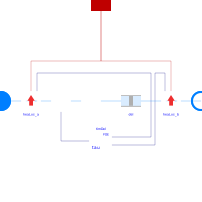
The model PlugFlowHeatLoss implements a heat loss in design direction, but leaves the enthalpy unchanged in opposite flow direction. Therefore it is used in front of and behind the time delay.
References
Full details on the model implementation and experimental validation can be found in:
van der Heijde, B., Fuchs, M., Ribas Tugores, C., Schweiger, G., Sartor, K., Basciotti, D., Müller,
D., Nytsch-Geusen, C., Wetter, M. and Helsen, L. (2017).
Dynamic equation-based thermo-hydraulic pipe model for district heating and cooling systems.
Energy Conversion and Management, vol. 151, p. 158-169.
doi: 10.1016/j.enconman.2017.08.072.
Parameters
| Type | Name | Default | Description |
|---|---|---|---|
| Modelica.SIunits.Length | dh | Hydraulic diameter (assuming a round cross section area) | |
| Modelica.SIunits.Length | length | Pipe length | |
| Real | R | Thermal resistance per unit length from fluid to boundary temperature | |
| Real | C | Thermal capacity per unit length of pipe | |
| Real | fac | 1 | Factor to take into account flow resistance of bends etc., fac=dp_nominal/dpStraightPipe_nominal |
| Modelica.SIunits.Length | thickness | Pipe wall thickness | |
| Real | ReC | 4000 | Reynolds number where transition to turbulent starts |
| Assumptions | |||
| Boolean | allowFlowReversal (from PartialTwoPort) | true | = false to simplify equations, assuming, but not enforcing, no flow reversal |
| Nominal condition | |||
| Modelica.SIunits.Velocity | v_nominal | Velocity at m_flow_nominal (used to compute default value for hydraulic diameter dh) | |
| Modelica.SIunits.MassFlowRate | m_flow_nominal | Nominal mass flow rate | |
| Advanced | |||
| Modelica.SIunits.MassFlowRate | m_flow_small | 1E-4*abs(m_flow_nominal) | Small mass flow rate for regularization of zero flow |
| Boolean | from_dp | false | = true, use m_flow = f(dp) else dp = f(m_flow) |
| Boolean | homotopyInitialization | true | = true, use homotopy method |
| Boolean | linearized | false | = true, use linear relation between m_flow and dp for any flow rate |
| Geometry | |||
| Modelica.SIunits.Height | roughness | 2.5e-5 | Average height of surface asperities (default: smooth steel pipe) |
| Initialization | |||
| Modelica.SIunits.Temperature | T_start_in | Medium.T_default | Initialization temperature at pipe inlet |
| Modelica.SIunits.Temperature | T_start_out | Medium.T_default | Initialization temperature at pipe outlet |
| Boolean | initDelay | false | Initialize delay for a constant mass flow rate if true, otherwise start from 0 |
| Modelica.SIunits.MassFlowRate | m_flow_start | 0 | |
Connectors
| Type | Name | Default | Description |
|---|---|---|---|
| Modelica.Fluid.Interfaces.FluidPort_a | port_a (from PartialTwoPort) | Fluid connector a (positive design flow direction is from port_a to port_b) | |
| Modelica.Fluid.Interfaces.FluidPort_b | port_b (from PartialTwoPort) | Fluid connector b (positive design flow direction is from port_a to port_b) | |
| Modelica.Thermal.HeatTransfer.Interfaces.HeatPort_a | heatPort | Heat port to connect environment (positive heat flow for heat loss to surroundings) |
Components
| Type | Name | Default | Description |
|---|---|---|---|
| IBPSA.Fluid.FixedResistances.HydraulicDiameter | res | Pressure drop calculation for this pipe | |
| IBPSA.Fluid.FixedResistances.BaseClasses.PlugFlow | del | Model for temperature wave propagation | |
| IBPSA.Fluid.FixedResistances.BaseClasses.PlugFlowHeatLoss | heaLos_a | Heat loss for flow from port_b to port_a | |
| IBPSA.Fluid.FixedResistances.BaseClasses.PlugFlowHeatLoss | heaLos_b | Heat loss for flow from port_a to port_b | |
| IBPSA.Fluid.Sensors.MassFlowRate | senMasFlo | Mass flow sensor | |
| IBPSA.Fluid.FixedResistances.BaseClasses.PlugFlowTransportDelay | timDel | Time delay |
Revisions
-
October 20, 2017, by Michael Wetter:
Replaced model that lumps flow resistance and transport delays with two separate models, as these are physically distinct processes. This also avoids one more layer of models.
Revised variable names and documentation to follow guidelines. -
July 4, 2016 by Bram van der Heijde:
IntroducepipVol. -
October 10, 2015 by Marcus Fuchs:
Copy Icon from KUL implementation and rename model. Replace resistance and temperature delay by an adiabatic pipe. -
September, 2015 by Marcus Fuchs:
First implementation.