User’s Guide
This package contains a model for photovoltaic–thermal (PVT)
collectors based on the ISO 9806:2013 quasi-dynamic thermal
procedure coupled with an internal electrical submodel.
Model description
Thermal part
The equations related to the heat losses and heat gains can be
found in the following models:
Thermal parameters used in the Quasi-dynamic thermal losses
model follow the ISO 9806:2013 quasi-dynamic thermal procedure.
Parameters obtained from other ISO 9806 test procedures, such as
the ISO 9806:2013 unglazed test or the ISO 9806:2017 quasi-dynamic
method, can be converted into the thermal parameter set required by
this model (c1 to c6, η0,
and Kd) using the procedure detailed in
SKN-N0474R0: Thermal Performance Parameter Conversion to ISO
9806-2017.
Electrical part
The equations and assumptions related to electrical part can be
found in the following model:
Electrical–thermal coupling
The internal heat transfer coefficient UAbsFluid
(visualised in Figure 1) is approximately calculated from datasheet
parameters:
UAbsFluid =
| (τ·α)eff – η0,el
· (c1 + c3·u + b1,el) |
|
(τ·α)eff – η0,el – (1 –
c6/η0,th·u) ·
η0,th |
- Here, (τ·α)eff = 0.901 for unglazed PVT
collectors as reported in Lämmle (2018), and 0.84 for
covered collectors.
- The electrical temperature‑dependence term is
b1,el = |γ| · Gnom, where γ is
the temperature coefficient of power (in % K−1) and
Gnom = 1000 W m−2.
- u is the in-plane wind speed. In this approximation,
u = 0 is used to derive UAbsFluid. The internal heat
transfer coefficient is only weakly dependent on external wind
speed when the datasheet thermal parameters are accurate (Stegmann
2011).
This approach removes the need for a hidden fit parameter: both
thermal and electrical coupling coefficients derive solely from
publicly available datasheet values.
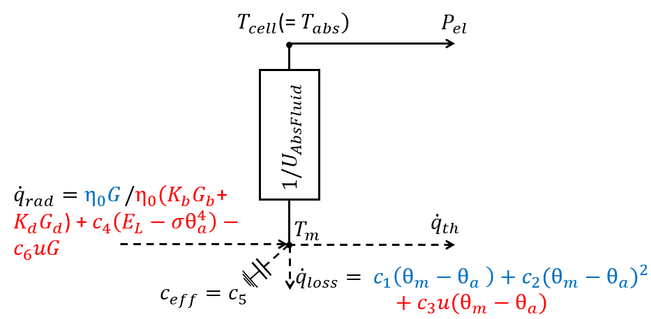
Figure 1: Two-node, one-capacitance thermal network for PVT
collectors (ISO 9806: dashed lines; extension: solid lines)
(Meertens et al., 2025).
References
- ISO 9806:2013. Solar thermal collectors
— Test methods. ISO.
- SKN-N0474R0.
Thermal Performance Parameter Conversion to ISO 9806-2017.
Solar Heat Europe, 2019.
- Stegmann, M.; Bertram, E.; Rockendorf, G.; Janßen, S. (2011).
Model of an Unglazed Photovoltaic Thermal Collector Based on
Standard Test Procedures. ISES Solar World Congress
proceedings. DOI: 10.18086/swc.2011.19.30
- Lämmle, M. (2018).
Thermal management of PVT collectors: development and modelling of
highly efficient glazed, flat plate PVT collectors with low
emissivity coatings and overheating protection. PhD thesis,
University of Freiburg. DOI: 10.6094/UNIFR/16446
- Dobos, A. P. (2014). PVWatts Version 5
Manual. NREL/TP-6A20-62641
- Meertens, L.; Jansen, J.; Helsen, L. (2025). Development and
Experimental Validation of an Unglazed Photovoltaic-Thermal
Collector Modelica Model that only needs Datasheet Parameters.
Submitted to the 16th International Modelica & FMI Conference,
Lucerne, Switzerland, Sep 8–10, 2025.
Generated at 2026-07-22T21:16:24Z by OpenModelicaOpenModelica 1.27.0 using
GenerateDoc.mos