Cascade level control with PI controllers
Description
Level control with two PI controllers, connected with a cascade
arrangement.
The considered system is a tank filled with water. The water level
is the process variable to be controlled.
The system (see the figure below) is composed by a tank and one
pipe connected to a linear valve that discharges the water in the
atmosphere. The valve actuator is represented by a first order
filter.
The control system is composed by the measurement part and the
controller. The pressure sensor measures the absolute
pressure
on the bottom of the tank.
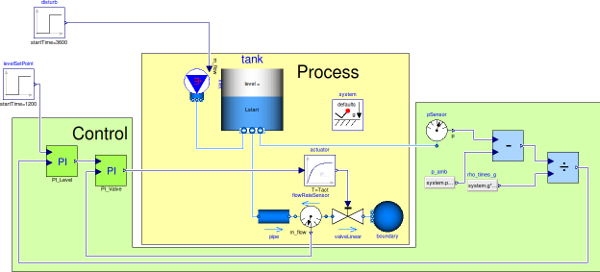
The measured pressure is subtracted from the atmospheric pressure
and then divided by the
gravity acceleration and the water density in order to obtain the
water level.
level = (p - p0)/(rho*g)
The PI controller, given the level measurement and the set point
reference compute the control action. Such a control
action is the water mass flow rate flowing through the pipe. Such a
mass flow rate becomes the set point reference for the second
PI that with its control action regulates the valve aperture
- CS = 0 valve closed,
- CS = 1 valve fully open
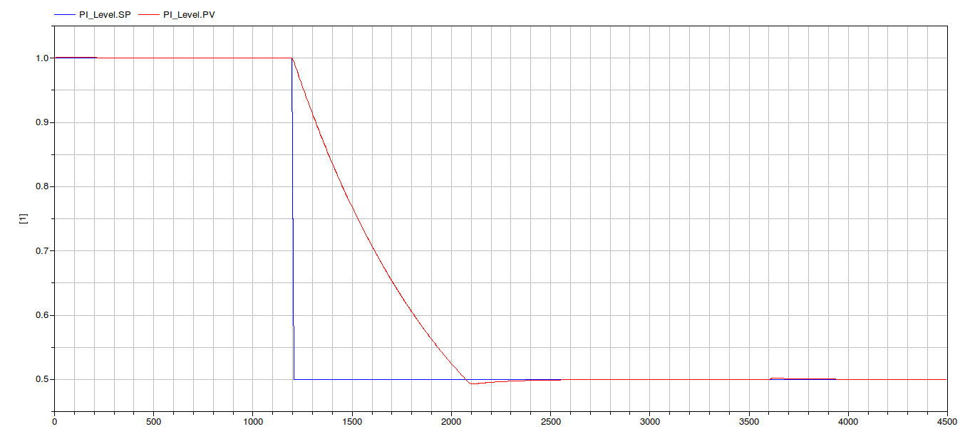
The tank is 2 m height, and the water level at t=0 is L = 1
m.
In the first phase the controller is asked to maintain the level at
the initial value (SP = 1 m), at t = 1200 s the level set
point
decrease as a step (SP = 0.5 m). The controller has to act on the
valve in order to decrease the water level to the desired
value.
A disturb represented by a water mass flow rate entering the tank,
becomes different from zero at time t = 3600 s.
Set Point reference, water level
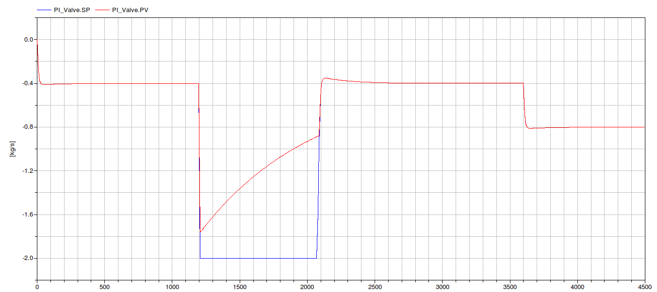
Set Point reference (the Control signal of the Level PI) and valve
command
The simulation can be perfomed at an initial stage assuming that
the controller is a continuous time one (Ts =
0) , that the math
operations are in double precision (FixedPoint
= false). In such a phase it is possible to concentrate on
the controller design.
Further stages
Once the controller has been designed and the parameters
assigned, one should introduce more details in order to simulate a
more realistic system. Please refers to the previous example (
LevelControl ) for more information.
- Industrial Control Systems (v 1.0.0) : April-May 2012
-
- List of revisions:
-
- 11 May 2012 (author: Marco Bonvini)
- Main Authors:
- Marco Bonvini; <bonvini@elet.polimi.it>
- Alberto Leva <leva@elet.polimi.it>
- Politecnico di Milano
- Dipartimento di Elettronica e Informazione
- Via Ponzio 34/5
- 20133 Milano - ITALIA -
- Copyright:
- Copyright © 2010-2012, Marco Bonvini and Alberto
Leva.
- The IndustrialControlSystems package is free
software; it can be redistributed and/or modified under the terms
of the Modelica license.
Generated at 2026-07-21T20:30:55Z by OpenModelicaOpenModelica 1.27.0 using
GenerateDoc.mos