Level control with a PI regulator.
The considered system is a tank filled with water. The water level
is the process variable to be controlled.
The system (see the figure below) is composed by a tank and one
pipe connected to a linear valve that discharges the water in the
atmosphere. The valve actuator is represented by a first order
filter.
The control system is composed by the measurement part and the
controller. The pressure sensor measures the absolute
pressure
on the bottom of the tank.
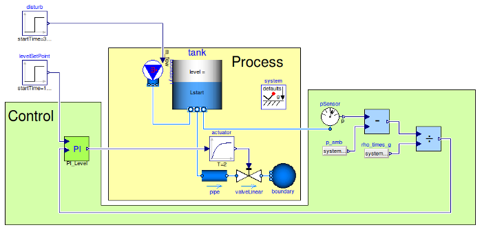
The measured pressure is subtracted from the atmospheric pressure
and then divided by the
gravity acceleration and the water density in order to obtain the
water level.
level = (p - p0)/(rho*g)The PI controller, given the level measurement and the set point reference compute the control action. Such a control
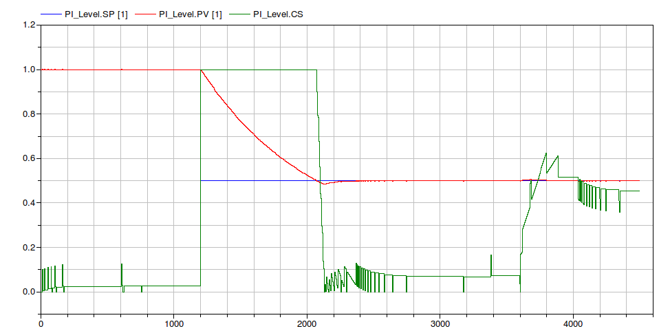
Once the controller has been designed and the parameters
assigned, one should introduce more details in order to simulate a
more realistic system. At first it is possible to introduce the
time discretisation and investigate the effect of the sampling
time.
Here follows the results for a sapling time Ts
= 5.
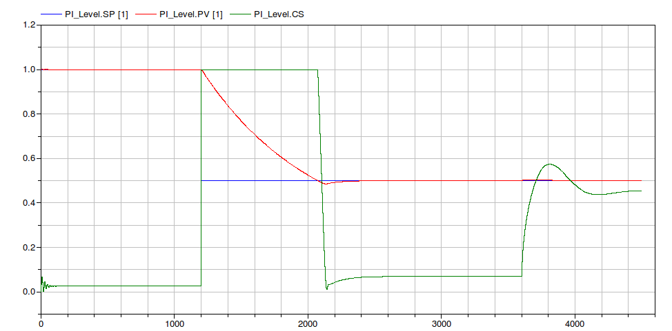
An additional level of detail can be the introduction of the fixed
point math operation in the level measurement process. In this case
has been choosen a number of bit Nbit =
24 this means that the integer number that can be
represented are comprises between MIN =
-8388609 and MAX = 8388608. At
the first stage, the measured pressure have to be subtracted of the
ambient one. In the wors case, the higher pressure value that can
be read as input from the math operation block is
101325 + 1000*9.81*2 = 120945that is more or less two order of magnitude less that the higher integer number MAX. This means that the input numbers can be multiplied by a scale factor comprises between 10 and 50. In this case the scale factor that has been choosen is sFactor = 20. In a similat way the scale factor of the division can be choosen. In this case sFactor = 500.