
modelPinEcho
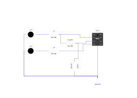
Extends from Modelica.Icons.Example (Icon for runnable examples).
Information
Demonstrator (outside the verification scenarios of requirements.md — except the dedicated scenario 7, which reuses this model): GP1 toggles (on/off every PERIOD=0.3 s, driven by pin_echo.py), GP2 reads back the real electrical state of GP1 (loopback loopR/loopC, not just the Python variable already known) before copying it to GP3. led1 shows the source, led3 the echo (no LED on GP2: almost the same potential as GP1, it would duplicate led1). The unused pins (GP0, GP4-GP7) are left unconnected.
GP1→GP2 loopback (loopR/loopC) rather than a plain wire: a direct connect(mcu.GP1, mcu.GP2) (or even a sensor + ideal voltage source, electrically equivalent) loses the driven voltage of GP1 in the results — observed empirically with several different loopback mechanisms, as long as GP2 stays a pure algebraic alias of GP1. Giving GP2 a real dynamic state through a negligible RC time constant (1 µs, with no visible effect on the 0.3 s blinking) works around the problem. See requirements.md for the full bisection trace.
Sync point needed between the write and the read-back: the script inserts a short time.sleep_ms(1) between pin1.on()/pin1.off() and the reading of pin2.value() — without this sync point, the read would see the state before the write (several consecutive immediate calls stay in the same pass on the C runtime side, without going back through the resolution of the Modelica circuit). See the user guide, page "machine / time API" (Limitations section), for the details of this behaviour — it is not a noticeable delay in the result (the input reactivity mechanism, already checked by the Gpio.InputReactivity scenario, wakes the script up as soon as the pin changes, without waiting for the deadline of this sleep).
Components
| Type | Name | Default | Description |
|---|---|---|---|
| MCU | mcu | scriptPath = Resources/Scripts/MCU/pin_echo.py | |
| Modelica.Electrical.Analog.Basic.Ground | ground | ||
| Modelica.Electrical.Analog.Basic.Resistor | r1 | limits the current of led1 (GP1, the source) | |
| Modelica.Electrical.Analog.Basic.Resistor | r3 | limits the current of led3 (GP3, the echo) | |
| MicroPythonMCU.Peripherals.LED | led1 | GP1: toggles (source) | |
| MicroPythonMCU.Peripherals.LED | led3 | GP3: copies what GP2 read on GP1 (echo) | |
| Modelica.Electrical.Analog.Basic.Resistor | loopR | GP1->GP2 loopback: link resistance. A direct connect() (or an exact algebraic equality through a sensor + ideal source) between GP1 and GP2 turned out to cancel the driven voltage of GP1 in the results (observed empirically, reproduced with several different loopback mechanisms) - worked around by giving GP2 a real dynamic state (see loopC) rather than an exact algebraic alias of GP1, see requirements.md | |
| Modelica.Electrical.Analog.Basic.Capacitor | loopC | Time constant of the loopback (R*C = 1 microsecond, completely negligible compared with PERIOD=0.3s of pin_echo.py): just enough for GP2 to be a real dynamic state rather than an exact algebraic alias of GP1, see loopR |