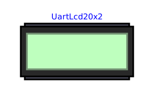
modelUartLcd20x2
Extends from Internal.Devices.PartialUartDevice (Base of the external serial devices: electrical link, decoding, two transmission modes, quantities exchanged with the model), Internal.Icons.TwoLineTextIcon (Icon of a 20x2 character display: two-line text rendering, shared by the display peripherals).
Information
The electrically real counterpart of Peripherals.Display. Where Display receives its text in one go through a causal logical link (machine.Display, no simulated baud rate), this one decodes a real serial frame arriving on its RX pin, bit by bit, at its own baud rate. A baud rate mismatch with the microcontroller therefore shows directly on the screen, as wrong characters.
On the embedded program side, writing a line ending with a line feed is enough: the device validates the line and triggers the display, exactly like the terminator of a command.
It extends two classes: Internal.Devices.PartialUartDevice for all the serial mechanics, and Internal.Icons.TwoLineTextIcon for the text rendering — the same 20x2 icon as Display, written only once. Beyond 20 characters, the line is truncated on the screen; the full text remains readable in the simulation log.
Write only: the device never answers nor transmits, nor returns anything to the model. Its TX pin (useTxPin) and its valueOut connector (useValueOutput) are therefore removed, like the settings of the request/response mechanics: only RX (and GND, VCC depending on the Electrical tab) remains to be wired.
Parameters
| Type | Name | Default | Description |
|---|---|---|---|
| Electrical › Supply | |||
| Boolean | useSupplyPin (from PartialSupplyPin) | false | Show the VCC supply pin: the peripheral is supplied by the circuit (its high levels follow VCC, its consumption IQ is drawn from VCC) - unchecked: ideal internal supply VOH, nothing to wire |
| Modelica.Units.SI.Voltage | VOH (from PartialSupplyPin) | Interfaces.VOH | Logic high voltage: ideal internal supply, high level of the outputs and of the pull-ups - with the VCC pin, the voltage of VCC is used instead |
| Modelica.Units.SI.Current | IQ (from PartialSupplyPin) | 1e-3 | Current drawn from VCC by the peripheral (quiescent consumption, outputs excluded) |
| Boolean | useGroundPin (from PartialSupplyPin) | true | Show the GND pin - unchecked: the peripheral is referenced to the simulation ground (0 V), nothing to wire |
| Electrical › Levels | |||
| Modelica.Units.SI.Voltage | VOL (from PartialUartPins) | Interfaces.VOL | Logic low voltage |
| Modelica.Units.SI.Voltage | VIH (from PartialUartPins) | Interfaces.VIH | Threshold above which an input reads high |
| Modelica.Units.SI.Voltage | VIL (from PartialUartPins) | Interfaces.VIL | Threshold below which an input reads low |
| Electrical › Impedances | |||
| Modelica.Units.SI.Resistance | ROut (from PartialUartPins) | Interfaces.ROut | Output series resistance |
| Modelica.Units.SI.Resistance | RPullUp (from PartialUartPins) | 1e6 | Pull-up of the RX input to the supply |
| Electrical › Pins | |||
| Boolean | useTxPin (from PartialUartPins) | true | Show the TX pin - unchecked for a device that never transmits (its output stage then stays unconnected) |
| Behaviour | |||
| Interfaces.UartBehaviour | behaviour (from PartialUartDevice) | Interfaces.UartBehaviour.Table | Origin of the behaviour: command table or Python script |
| String | scriptPath (from PartialUartDevice) | "" | Script .py describing the behaviour of the device (Script mode) |
| Serial link | |||
| Integer | baudrate (from PartialUartDevice) | 1200 | Link speed, in baud |
| Integer | dataBits (from PartialUartDevice) | 8 | Number of data bits of a frame (5 to 8, as machine.UART bits=) |
| Interfaces.UartParity | parity (from PartialUartDevice) | Interfaces.UartParity.None | Parity of a frame (as machine.UART parity=: None, 0 = even, 1 = odd) |
| Integer | stopBits (from PartialUartDevice) | 1 | Number of stop bits (1 or 2, as machine.UART stop=) |
| String | terminator (from PartialUartDevice) | "\n" | Character marking the end of a received command (only the first character is kept) |
| Simulation | |||
| Modelica.Units.SI.Time | tickPeriod (from PartialUartDevice) | 0.1 | Period of the minimal sync point: a safety net, the actual pace comes from the engine's deadlines |
| Table › Request / response | |||
| Boolean | respondEnabled (from PartialUartDevice) | true | Reply to the recognised commands |
| String | commandTable (from PartialUartDevice) | "" | Table "CMD=>REPLY|CMD=>REPLY"; "|" and "=>" are reserved. {vN} inserts valueIn[N] into the reply, {oN} captures a number of the command into valueOut[N] |
| Modelica.Units.SI.Time | responseDelay (from PartialUartDevice) | 0.002 | Delay between the recognition of a command and the start of the reply |
| Boolean | echoEnabled (from PartialUartDevice) | false | Send back every received byte unchanged |
| Table › Periodic transmission | |||
| Boolean | periodicEnabled (from PartialUartDevice) | false | Transmit spontaneously, without being asked |
| Modelica.Units.SI.Time | period (from PartialUartDevice) | 1 | Period of the spontaneous transmission (in Script mode: call period of on_tick) |
| String | periodicTemplate (from PartialUartDevice) | "" | Template of the periodically transmitted frame ({vN} inserts valueIn[N]) |
| Inputs / outputs › Inputs ({vN}, inserted into transmitted frames) | |||
| Boolean | useValueInput (from PartialUartDevice) | false | Take the quantities from the valueIn connector rather than from a constant |
| Integer | nIn (from PartialUartDevice) | 1 | Number of quantities received from the model |
| Real | fixedValue (from PartialUartDevice) | 0 | Value used when valueIn is not connected |
| Inputs / outputs › Outputs ({oN}, captured from received frames) | |||
| Boolean | useValueOutput (from PartialUartDevice) | true | Show the valueOut connector - unchecked for a device that returns nothing to the model |
| Integer | nOut (from PartialUartDevice) | 1 | Number of quantities returned to the model - leave the connector unconnected if unused |
| Real | valueOutStart (from PartialUartDevice) | 0 | Value of valueOut before any capture |
Connectors
| Type | Name | Default | Description |
|---|---|---|---|
| Modelica.Electrical.Analog.Interfaces.NegativePin | GND (from PartialSupplyPin) | Common reference (ground), to be connected to the microcontroller's one - shown when useGroundPin is checked | |
| Modelica.Electrical.Analog.Interfaces.PositivePin | VCC (from PartialSupplyPin) | Supply of the peripheral (e.g. 3V3(OUT) of a Raspberry Pi Pico) - shown when useSupplyPin is checked | |
| Modelica.Electrical.Analog.Interfaces.PositivePin | TX (from PartialUartPins) | Transmission of the device - to be connected to the receive pin of the microcontroller - shown when useTxPin is checked | |
| Modelica.Electrical.Analog.Interfaces.PositivePin | RX (from PartialUartPins) | Reception of the device - to be connected to the transmit pin of the microcontroller | |
| Modelica.Blocks.Interfaces.RealInput[nIn] | valueIn (from PartialUartDevice) | Quantities supplied by the model, inserted into the transmitted frames by {v1}..{vN} | |
| Modelica.Blocks.Interfaces.RealOutput[nOut] | valueOut (from PartialUartDevice) | Quantities extracted from the received frames by {o1}..{oN} - the device then becomes an actuator |
Components
| Type | Name | Default | Description |
|---|---|---|---|
| Boolean | txActive (from PartialUartDevice) | A frame is being transmitted | |
| Boolean | rxBusy (from PartialUartDevice) | A frame is being received | |
| String | lastRx (from PartialUartDevice) | Last complete line received | |
| String | lastTx (from PartialUartDevice) | Last payload transmitted | |
| Integer[Interfaces.DISPLAY_COLS] | line1CharCode (from TwoLineTextIcon) | ASCII codes of line 1 (current message) - to be fed by the extending model, typically through Internal.Functions.StringToCharCodes | |
| Integer[Interfaces.DISPLAY_COLS] | line2CharCode (from TwoLineTextIcon) | ASCII codes of line 2 (previous message), for scrolling |