modelRPi_Pico
Extends from Internal.Boards.PartialUsbBoard (Common base of the boards supplied through USB (RPi_Pico, MicroBit_v2): the USB supply parameters are written here once - each board keeps its own supply chain (pins, components, wiring), whose placement and topology are board-specific).
Information
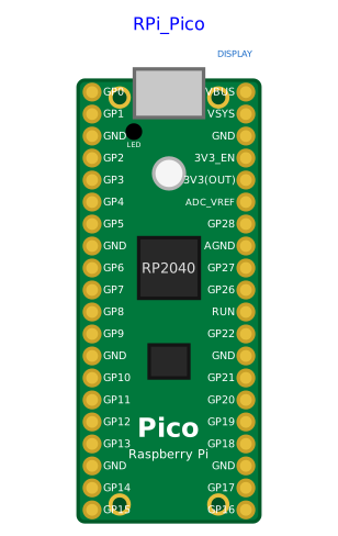
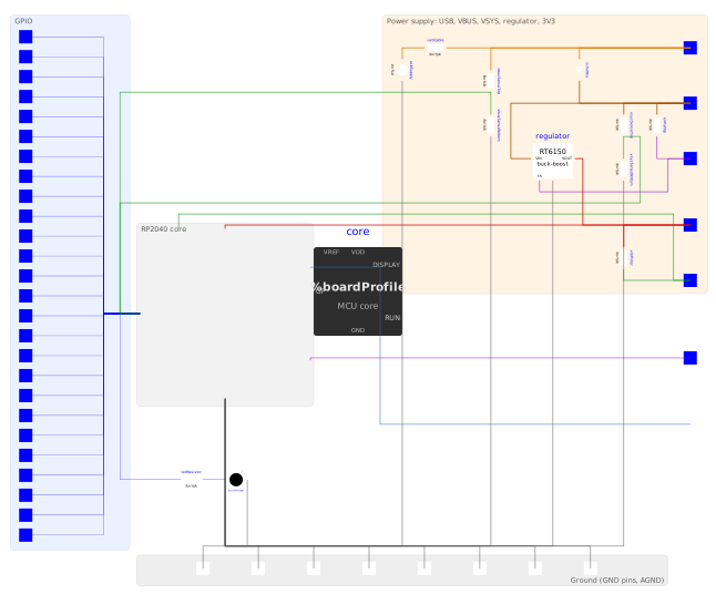
Replica of the Raspberry Pi Pico board (RP2040): real pinout (40 pins, viewed from above, USB connector at the top) and real dimensions (21 x 51 mm, 2.54 mm pitch, rows 17.78 mm apart), and its power supply. It contains the same programmable core as MCU (Internal.Boards.McuCore: Python program, machine API, sync point), wired to the power components of the board — see the internal diagram. The pins are supplied by the 3.3 V rail of the board, and the program only runs while the board is supplied.
Power supply
usbConnected(true by default, lightning bolt on the USB connector of the icon): the USB cable supplies 5 V onVBUS— the board runs without wiring anything, like a Pico plugged into the computer.VBUSfeedsVSYSthrough a Schottky diode (about 0.3 V).VSYS(1.8 to 5.5 V) can also be supplied directly, typically by a battery, withusbConnected = false.- The buck-boost regulator (
Internal.Boards.Rt6150, averaged model: efficiencyeta, undervoltage lockout) makes the 3.3 V rail fromVSYS;3V3_EN(pulled up toVSYS) switches it off when grounded. The rail supplies the RP2040 and the flash (ICore), the pins (high level and pull-ups: the current of an LED on a pin is drawn from it) and the3V3(OUT)pin for external circuits. ADC_VREF= 3V3 filtered through 200 Ohm: it is the reference ofmachine.ADC.- Internal sensing, as on the board:
Pin(24)reads the presence ofVBUS,ADC(3)(GPIO29) readsVSYS/3,ADC(4)reads the temperature sensor (dieTemperature).
Power-on and power loss: the program (boot.py/main.py or the script) starts the first time the 3.3 V rail exceeds VPowerOn with RUN high, and time.ticks_ms() counts from this instant. If the rail falls below VPowerOff or RUN is grounded afterwards, the program is stopped for good (warning in the log) and the pins are released; a restart when the supply comes back is not simulated.
Differences with MCU
- All the pins of the board:
GP0-GP22,GP26-GP28; ADC only onGP26-GP28(ADC(0)-ADC(2)), as on the RP2040. - UART and I2C follow the pin multiplexing of the RP2040 (e.g.
UART(0): TX on GP0, 12, 16 or 28) and the default pins of the rp2 port;UART(0)andUART(1)(andI2C(0)/I2C(1)) are both accepted, but only one at a time (single engine in the simulation).SoftI2Caccepts any pins. - The on-board LED (
Pin(25)orPin("LED")) is drawn at its real place on the icon.
The Display0 logical link to the educational displays is kept (top of the icon), although it does not exist on the real board. See requirements.md, decision "Carte Raspberry Pi Pico et alimentation".
Parameters
| Type | Name | Default | Description |
|---|---|---|---|
| Modelica.Units.SI.Time | tickPeriod (from PartialMcuSettings) | 0.1 | Period of the minimal sync point (output freshness if the script never sleeps) |
| Python script | |||
| String | scriptPath (from PartialMcuSettings) | Modelica.Utilities.Files.loadResource("modelica://MicroPythonMCU/Resources/Scripts/MCU/demo.py") | Path of the user script (.py) - with an active file system, run after boot.py instead of main.py; empty = main.py from the flash |
| Boolean | addScriptDirToPath (from PartialMcuSettings) | true | Make the .py files next to the script importable (e.g. import my_module) - mimics the real Pico (flash root folder on sys.path) |
| String | libraryPath (from PartialMcuSettings) | "" | Optional: a .py file from a shared library folder to make importable (the folder containing this file is added to the module search path) - leave empty if unused |
| File system › Simulated flash | |||
| Boolean | fsEnabled (from PartialMcuSettings) | false | Enable the file system (simulated flash) - disabled: open() and os raise OSError |
| String | fsSource (from PartialMcuSettings) | "" | Initial image of the flash (folder: data, boot.py, main.py, lib/), copied at each simulation and never modified - any file of the folder, the folder path or a modelica:// URI; empty = blank flash, only the script runs |
| String | fsWorkspace (from PartialMcuSettings) | "." | Workspace: folder where each simulation creates its copy, named <instance>_<FS name>_<date>_<time> (created if missing) - "." or relative path = from the simulation folder; full path of the copy shown in the log |
| Boolean | fsOpenExplorer (from PartialMcuSettings) | true | Open Windows Explorer on the copy at the end of the simulation |
| Execution time | |||
| Modelica.Units.SI.Time | gpioOpTime (from PartialMcuSettings) | 5e-6 | Execution time of a pin access (Pin.value(), on(), off()): two writes without sleep() give a pulse of this width (bit-banging) - order of magnitude of MicroPython on RP2040; 0 = instantaneous accesses |
| Modelica.Units.SI.Time | hangWarningTime (from PartialMcuSettings) | 10 | Real (wall-clock) time after which a warning is logged if the script does not let the simulation advance (loop without sleep() nor pin access, or with gpioOpTime = 0) - the simulation keeps waiting; 0 = no warning |
| Debugging | |||
| Boolean | debugEnabled (from PartialMcuSettings) | false | Debug the program with VS Code: at the start of the simulation, the microcontroller waits until VS Code attaches (debugpy, Run and Debug > attach to localhost:debugPort); simulated time stays frozen while the program is paused - one microcontroller per model |
| Integer | debugPort (from PartialMcuSettings) | 5678 | Local TCP port on which the debugger (debugpy) listens - the port of the VS Code attach configuration |
| Electrical › Logic levels | |||
| Modelica.Units.SI.Voltage | VOL (from PartialMcuSettings) | Interfaces.VOL | Logic low voltage |
| Modelica.Units.SI.Voltage | VIH (from PartialMcuSettings) | Interfaces.VIH | Threshold above which an input reads high |
| Modelica.Units.SI.Voltage | VIL (from PartialMcuSettings) | Interfaces.VIL | Threshold below which an input reads low |
| Electrical › Output stages | |||
| Modelica.Units.SI.Resistance | ROut (from PartialMcuSettings) | Interfaces.ROut | Output series resistance (drive strength) |
| Modelica.Units.SI.Resistance | ledSeriesR | 330 | Series resistance of the on-board LED (internal, GP25) |
| Electrical › Input stages | |||
| Modelica.Units.SI.Resistance | RPullUp (from PartialMcuSettings) | Interfaces.RPull | Internal pull-up resistor to the supply, switched on by Pin(n, mode, Pin.PULL_UP) and by I2C() on SCL/SDA |
| Modelica.Units.SI.Resistance | RPullDown (from PartialMcuSettings) | Interfaces.RPull | Internal pull-down resistor to GND, switched on by Pin(n, mode, Pin.PULL_DOWN) |
| Modelica.Units.SI.Conductance | GOff (from PartialMcuSettings) | Interfaces.GOff | Leakage of a pin that does not drive its line (input, released I2C line), towards GND: 1e-9 S = 1 GOhm |
| Power supply › Consumption | |||
| Modelica.Units.SI.Current | ICore (from PartialBoard) | 0.02 | Current drawn from the supply rail by the core and its memory while supplied (program running, pins excluded) |
| Power supply › Power-on | |||
| Modelica.Units.SI.Voltage | VPowerOn (from PartialBoard) | 1.8 | Supply rail voltage above which the core starts (power-on reset) |
| Modelica.Units.SI.Voltage | VPowerOff (from PartialBoard) | 1.6 | Supply rail voltage below which a running core stops for good (brown-out) |
| Power supply › USB | |||
| Boolean | usbConnected (from PartialUsbBoard) | true | USB cable plugged in: 5 V through the USB connector (the board runs without any wiring) - false to supply the board through its supply pin |
| Modelica.Units.SI.Voltage | VUsb (from PartialUsbBoard) | 5 | Voltage of the USB supply |
| Modelica.Units.SI.Resistance | RUsb (from PartialUsbBoard) | 0.2 | Resistance of the USB cable and connector |
| Power supply › Regulator | |||
| Real | eta (from PartialUsbBoard) | 0.9 | Efficiency of the regulator |
| Power supply › Temperature sensor | |||
| Modelica.Units.NonSI.Temperature_degC | dieTemperature | 27 | Temperature of the RP2040, read by machine.ADC(4) |
Connectors
| Type | Name | Default | Description |
|---|---|---|---|
| Modelica.Electrical.Analog.Interfaces.PositivePin | GP0 | GPIO 0, physical pin 1 (machine.Pin(0)) | |
| Modelica.Electrical.Analog.Interfaces.PositivePin | GP1 | GPIO 1, physical pin 2 (machine.Pin(1)) | |
| Modelica.Electrical.Analog.Interfaces.NegativePin | GND_3 | Ground, physical pin 3 (all the GND pins and AGND are connected together) | |
| Modelica.Electrical.Analog.Interfaces.PositivePin | GP2 | GPIO 2, physical pin 4 (machine.Pin(2)) | |
| Modelica.Electrical.Analog.Interfaces.PositivePin | GP3 | GPIO 3, physical pin 5 (machine.Pin(3)) | |
| Modelica.Electrical.Analog.Interfaces.PositivePin | GP4 | GPIO 4, physical pin 6 (machine.Pin(4)) | |
| Modelica.Electrical.Analog.Interfaces.PositivePin | GP5 | GPIO 5, physical pin 7 (machine.Pin(5)) | |
| Modelica.Electrical.Analog.Interfaces.NegativePin | GND_8 | Ground, physical pin 8 (all the GND pins and AGND are connected together) | |
| Modelica.Electrical.Analog.Interfaces.PositivePin | GP6 | GPIO 6, physical pin 9 (machine.Pin(6)) | |
| Modelica.Electrical.Analog.Interfaces.PositivePin | GP7 | GPIO 7, physical pin 10 (machine.Pin(7)) | |
| Modelica.Electrical.Analog.Interfaces.PositivePin | GP8 | GPIO 8, physical pin 11 (machine.Pin(8)) | |
| Modelica.Electrical.Analog.Interfaces.PositivePin | GP9 | GPIO 9, physical pin 12 (machine.Pin(9)) | |
| Modelica.Electrical.Analog.Interfaces.NegativePin | GND_13 | Ground, physical pin 13 (all the GND pins and AGND are connected together) | |
| Modelica.Electrical.Analog.Interfaces.PositivePin | GP10 | GPIO 10, physical pin 14 (machine.Pin(10)) | |
| Modelica.Electrical.Analog.Interfaces.PositivePin | GP11 | GPIO 11, physical pin 15 (machine.Pin(11)) | |
| Modelica.Electrical.Analog.Interfaces.PositivePin | GP12 | GPIO 12, physical pin 16 (machine.Pin(12)) | |
| Modelica.Electrical.Analog.Interfaces.PositivePin | GP13 | GPIO 13, physical pin 17 (machine.Pin(13)) | |
| Modelica.Electrical.Analog.Interfaces.NegativePin | GND_18 | Ground, physical pin 18 (all the GND pins and AGND are connected together) | |
| Modelica.Electrical.Analog.Interfaces.PositivePin | GP14 | GPIO 14, physical pin 19 (machine.Pin(14)) | |
| Modelica.Electrical.Analog.Interfaces.PositivePin | GP15 | GPIO 15, physical pin 20 (machine.Pin(15)) | |
| Modelica.Electrical.Analog.Interfaces.PositivePin | VBUS | Micro-USB input voltage, physical pin 40: 5 V from the USB connector when usbConnected, otherwise free (an external 5 V supply can be connected here) | |
| Modelica.Electrical.Analog.Interfaces.PositivePin | VSYS | Main system input, physical pin 39: 1.8 to 5.5 V, supplied from VBUS through a Schottky diode, or directly from a battery | |
| Modelica.Electrical.Analog.Interfaces.NegativePin | GND_38 | Ground, physical pin 38 (all the GND pins and AGND are connected together) | |
| Modelica.Electrical.Analog.Interfaces.PositivePin | V3V3_EN | Enable of the 3.3 V regulator (3V3_EN), physical pin 37: pulled up to VSYS by 100 kOhm, to ground to switch the regulator off | |
| Modelica.Electrical.Analog.Interfaces.PositivePin | V3V3 | 3.3 V output of the regulator (3V3(OUT)), physical pin 36: supplies external circuits (keep the load under 300 mA) | |
| Modelica.Electrical.Analog.Interfaces.PositivePin | ADC_VREF | ADC reference voltage, physical pin 35: 3V3 filtered through 200 Ohm on the board; can be driven by an external reference | |
| Modelica.Electrical.Analog.Interfaces.PositivePin | GP28 | GPIO 28, physical pin 34 (machine.Pin(28), machine.ADC(2)) | |
| Modelica.Electrical.Analog.Interfaces.NegativePin | AGND | Analog ground of the ADC, physical pin 33 (connected to GND) | |
| Modelica.Electrical.Analog.Interfaces.PositivePin | GP27 | GPIO 27, physical pin 32 (machine.Pin(27), machine.ADC(1)) | |
| Modelica.Electrical.Analog.Interfaces.PositivePin | GP26 | GPIO 26, physical pin 31 (machine.Pin(26), machine.ADC(0)) | |
| Modelica.Electrical.Analog.Interfaces.PositivePin | RUN | RP2040 enable, physical pin 30: internal pull-up to 3V3; to ground, the RP2040 is held in reset (the program stops for good, a restart is not simulated) | |
| Modelica.Electrical.Analog.Interfaces.PositivePin | GP22 | GPIO 22, physical pin 29 (machine.Pin(22)) | |
| Modelica.Electrical.Analog.Interfaces.NegativePin | GND_28 | Ground, physical pin 28 (all the GND pins and AGND are connected together) | |
| Modelica.Electrical.Analog.Interfaces.PositivePin | GP21 | GPIO 21, physical pin 27 (machine.Pin(21)) | |
| Modelica.Electrical.Analog.Interfaces.PositivePin | GP20 | GPIO 20, physical pin 26 (machine.Pin(20)) | |
| Modelica.Electrical.Analog.Interfaces.PositivePin | GP19 | GPIO 19, physical pin 25 (machine.Pin(19)) | |
| Modelica.Electrical.Analog.Interfaces.PositivePin | GP18 | GPIO 18, physical pin 24 (machine.Pin(18)) | |
| Modelica.Electrical.Analog.Interfaces.NegativePin | GND_23 | Ground, physical pin 23 (all the GND pins and AGND are connected together) | |
| Modelica.Electrical.Analog.Interfaces.PositivePin | GP17 | GPIO 17, physical pin 22 (machine.Pin(17)) | |
| Modelica.Electrical.Analog.Interfaces.PositivePin | GP16 | GPIO 16, physical pin 21 (machine.Pin(16)) | |
| Interfaces.DisplayLinkOutput | Display0 | Logical link to an educational display peripheral (machine.Display(0).write()) - not on the real board: simplified causal link, see requirements.md decision "Périphérique d'affichage pédagogique" |
Components
| Type | Name | Default | Description |
|---|---|---|---|
| Internal.Boards.PartialMcuCore | core (from PartialBoard) | Programmable core, public like in the boards so that its plotted variables (powerGood, supplyOk...) stay in the simulation results - partial: every board redeclares it (McuCore); pin table (nPins, pinIds, pinCaps), board profile and on-board devices are set by the board in the modifier of its extends, pins in the order of pinIds | |
| Internal.Boards.Rt6150 | regulator | Buck-boost regulator VSYS -> 3.3 V (RT6150B) | |
| MicroPythonMCU.Peripherals.LED | builtinLed | On-board LED (GPIO25) | |
| Modelica.Units.SI.Voltage | vRail | V3V3.v - core.gnd.v | Voltage of the 3.3 V rail (3V3(OUT)) |
| Modelica.Units.SI.Voltage | vSys | VSYS.v - core.gnd.v | Voltage of VSYS |
| Modelica.Units.SI.Current | iSys | regulator.iIn | Current drawn from VSYS by the regulator |