The M_OLine is a multi line model which consists of
several segments and several single lines. Each segment consists of
resistors and inductors that are connected in series in each single
line, and of capacitors and conductors both between the lines and
to the ground. The inductors are coupled to each other like in the
M_Transformer
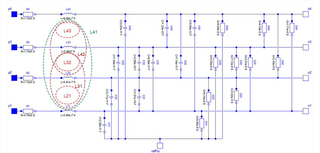
model. The following picture shows the schematic of a segment with
four single lines (lines=4):
Note that the user can choose whether the optional "refPin" is active (so that it can be connected to any other pin), otherwise the internal "ground" is used. This is done with the checkbox useInternalGround, true by default (for compatibility with previous versions). Obviously the potential of the internal ground is always zero, its current can be accessed for plotting.
The complete multi line consists of N segments and an auxiliary segment_last:
-- segment_1 -- segment_2 -- ... --
segment_N -- segment_last --
In the picture of the segment can be seen, that a single segment
is asymmetrical. Connecting such asymmetrical segments in a series
forces also an asymmetrical multi line. To design a symmetrical
model which is useful for coupling and which guaranties the same
pin properties, in segment_1 only half valued
resistors and inductors are used. The remaining resistors and
inductors are at the other end of the line within the auxiliary
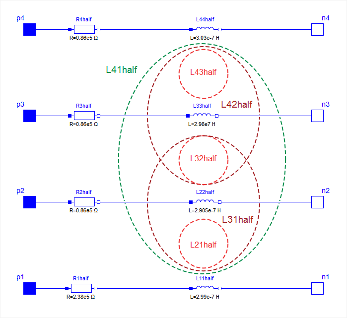
segment_last. For the example with 4 lines the
schematic of segment_last is like this:
The number of the capacitors and conductors depends on the
number of single lines that are used, because each line is coupled
to every other line by both a capacitor and a conductor. One line
consists of at least two segments. Inside the
model M_OLine the model segment is used.
This model represents one segment which is build as described
above. For modelling the inductances and their mutual couplings the
model M_Transformer
is used. To fill the resistance vector, resistance values as many
as lines are needed, e.g., if there are four lines, four
resistances are needed. For example for a microelectronic line of
0.1m length, a sensible resistance-vector would be R=[4.76e5,
1.72e5, 1.72e5, 1.72e5].
Filling the matrices of the inductances, capacitances and
conductances is a bit more complicated, because those components
occur also between two lines and not only (like the resistor) in
one line. The entries of the matrices are given by the user in form
of a vector. The vector length dim_vector_lgc is
calculated by:
dim_vector_lgc = lines*(lines+1)/2
Inside the model a symmetrical inductance matrix, a symmetrical capacitance matrix and a symmetrical conductance matrix are built out of the entries of the vectors given by the user. The way of building is the same for each matrix, so the approach for filling one of the matrices will be shown in the the example below.
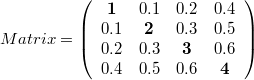
The number of lines is assumed to be four. To build the matrix, the model needs the values from the main diagonal and from the positions that are below the main diagonal. To get the following matrix
the vector with dim_vector_lgc=4*5/2=10 has to appear in the following way: vector = [1, 0.1, 0.2, 0.4, 2, 0.3 0.5, 3, 0.6, 4]
For the example of a microelectronic line of 0.1m length, which
is used as default example for the M_OLine model, a
sensible inductance-matrix would be:
For the example of a microelectronic line of 0.1m length, which
is used as default example for the M_OLine model, a
sensible capacitance-matrix would be:
For the example of a microelectronic line of 0.1m length, which
is used as default example for the M_OLine model, a
sensible conductance-matrix would be:
The user has the possibility to enable a conditional heatport.
If so, the M_OLine can be connected to a thermal
network. If the parameter alpha is set to a value
different than zero, the M_OLine becomes temperature
sensitive due to their resistors which resistances are calculated
by
R_actual = R*(1 + alpha*(heatPort.T - T_ref))
and conductors calculated by
G_actual = G/(1 + alpha*(heatPort.T - T_ref))
| Name | Description |
|---|---|
| Multiple line segment model | |
| Multiple line last segment model |
| Version | Revision | Date | Author | Comment |
|---|---|---|---|---|
| 4163 | 2010-09-11 | Dietmar Winkler | Documentation corrected according to documentation guidelines. | |
| 2008-11-24 | Kristin Majetta | Documentation added. | ||
| 2007-02-26 | Kristin Majetta | Initially implemented |