
modelPolyphaseRectifier
Demonstrate a polyphase diode rectifier
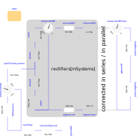
Extends from Icons.Example (Icon for runnable examples).
Information
This example demonstrates a polyphase system with a rectifier per subsystem.
Note that the interaction between the subsystems is damped by the DC resistors and inductors.
You may try different number of phases 2 ≤ m, as well as connect the rectifiers with different number of parallel branches, and investigate AC values:
- AC power
analysatorAC.pTotal(sum of all phases) - AC current
analysatorAC.iFeed[m](1st harmonic rms) - AC voltage
analysatorAC.vLN[m](1st harmonic rms, line to neutral) - AC voltage
analysatorAC.vLL[m](1st harmonic rms, line to line)
as well as DC values per subsystem (rectifier) and total (load):
- DC power total
analysatorAC.pDC(mean) - DC current total
analysatorAC.iDC(mean) - DC voltage total
analysatorAC.vDC(mean)
Parameters
| Type | Name | Default | Description |
|---|---|---|---|
| Utilities.PolyphaseRectifierData | data |
Components
| Type | Name | Default | Description |
|---|---|---|---|
| Sources.SineVoltage | sineVoltage | ||
| Basic.MultiStarResistance | multiStar | ||
| Analog.Basic.Resistor | resistor2ground | ||
| Analog.Basic.Ground | groundAC | ||
| Utilities.AnalysatorAC | analysatorAC | ||
| Basic.SplitToSubsystems | splitToSubsystems | ||
| Ideal.IdealDiode[data.mSystems] | diode1 | ||
| Ideal.IdealDiode[data.mSystems] | diode2 | ||
| Basic.Star[data.mSystems] | star1 | ||
| Basic.Star[data.mSystems] | star2 | ||
| Analog.Basic.Resistor[data.mSystems] | resistorDC1 | ||
| Analog.Basic.Inductor[data.mSystems] | inductorDC1 | ||
| Utilities.AnalysatorDC[data.mSystems] | analysatorDC | ||
| Analog.Basic.Resistor[data.mSystems] | resistorDC2 | ||
| Analog.Basic.Inductor[data.mSystems] | inductorDC2 | ||
| Utilities.AnalysatorDC | analysatorDCload | ||
| Analog.Basic.Resistor | loadResistor1 | ||
| Analog.Basic.Resistor | loadResistor2 | ||
| Analog.Basic.Ground | groundDC |