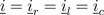
A simple example of a series connection of a resistor, an inductor and a capacitor as depicted in Fig. 1 should be explained in the following. For various frequencies, the voltage drops across the resistor, the inductor and the capacitor should be determined.
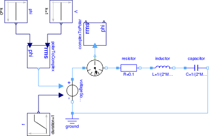 |
The voltage drop across the resistor

and the inductor

and the capacitor

add up to the total voltage

as illustrated in the phasor diagram of Fig. 2.
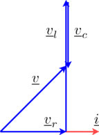 |
Due to the series connection of the resistor, inductor and capacitor, the three currents are all equal: