
modelLogicalNetwork1
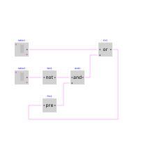
Demonstrates the usage of logical blocks
Extends from Modelica.Icons.Example (Icon for runnable examples).
Information
This example demonstrates a network of logical blocks. Note, that the Boolean values of the input and output signals are visualized in the diagram animation, by the small "circles" close to the connectors. If a "circle" is "white", the signal is false. It a "circle" is "green", the signal is true.
Components
| Type | Name | Default | Description |
|---|---|---|---|
| Sources.BooleanTable | table2 | ||
| Sources.BooleanTable | table1 | ||
| Logical.Not | Not1 | ||
| Logical.And | And1 | ||
| Logical.Or | Or1 | ||
| Logical.Pre | Pre1 |