blockAssignClockToTriggerHold

Extends from Clocked.ClockSignals.Interfaces.ClockedBlockIcon (Basic graphical layout of block where at least one input or output is a clocked variable).
Information
This block creates a Boolean, continuous time, trigger signal whenever the clock of the input signal is active.
A particular use-case in which that block might be useful is the combination of "old-style" sampled blocks (i.e., "unclocked" discrete control functions implemented using equations between "when trigger then" clauses) with clocked blocks.
Example
The following
example
samples a sine signal with a periodic clock of 20 ms period. After that a continuous time Boolean trigger signal is generated at every clock tick of that sampled signal. The generated signal is used as trigger signal for an "old-style" TriggeredSampler block from the Modelica.Blocks.Discrete package:
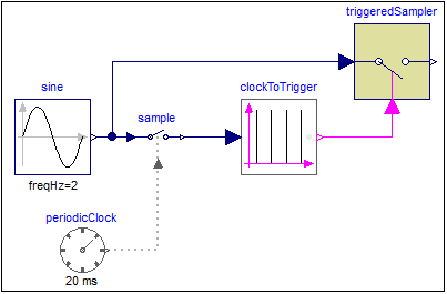 |
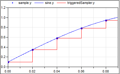 |
|
| model | simulation result |
Note, that it is clearly visible in the plot that the "old-style" discrete variables have an implicit zero-order hold semantics, while the new clocked variables are only active whenever their associated clock ticks. Just compare variable sample.y (clocked) with triggeredSampler.y (unclocked) to observe the difference.
Parameters
| Type | Name | Default | Description |
|---|---|---|---|
| Boolean | y_start | false | Initial value of output signal |
Connectors
| Type | Name | Default | Description |
|---|---|---|---|
| Modelica.Blocks.Interfaces.RealInput | u | ||
| Modelica.Blocks.Interfaces.BooleanOutput | y | Connector of Boolean output signal |