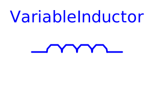
modelVariableInductor

Extends from Modelica.Electrical.Analog.Interfaces.OnePort (Component with two electrical pins p and n and current i from p to n).
Information
The linear inductor connects the branch voltage v with the branch current i by
v = d Psi/dt with Psi = L * i .
The inductance L is as input signal.
It is required that L ≥ 0, otherwise an assertion is raised. To avoid a variable index system, L = Lmin, if 0 ≤ L < Lmin, where Lmin is a parameter with default value Modelica.Constants.eps.
Besides the Lmin parameter the inductor model has got the two parameters IC and UIC that belong together. With the IC parameter the user can specify an initial value of the current that flows through the inductor.
Hence the inductor has an initial current at the beginning of the simulation. The other parameter UIC is of type Boolean. If UIC is true, the simulation tool uses
the IC value at the initial calculation by adding the equation i= IC. If UIC is false, the IC value can be used (but it does not need to!) to calculate the initial values in order to simplify the numerical algorithms of initial calculation.
Parameters
| Type | Name | Default | Description |
|---|---|---|---|
| SI.Inductance | Lmin | Modelica.Constants.eps | Lower bound for variable inductance |
| SI.Current | IC | 0 | Initial Value |
| Boolean | UIC | false | Decision if initial value IC shall be used |
Connectors
| Type | Name | Default | Description |
|---|---|---|---|
| PositivePin | p (from TwoPin) | Positive electrical pin | |
| NegativePin | n (from TwoPin) | Negative electrical pin | |
| Modelica.Blocks.Interfaces.RealInput | L |
Components
| Type | Name | Default | Description |
|---|---|---|---|
| SI.Voltage | v (from TwoPin) | Voltage drop of the two pins (= p.v - n.v) | |
| SI.Current | i (from OnePort) | Current flowing from pin p to pin n | |
| SI.MagneticFlux | Psi |
Revisions
- June 7, 2004
by Christoph Clauss
changed, docu added
- April 30, 2004
by Anton Haumer
implemented.