
modelCompareTransformers
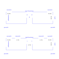
Extends from Modelica.Icons.Example (Icon for runnable examples).
Information
This example is to demonstrate the behaviour of transformer models. The Basic.Transformer, which consists of mutual coupled inductors, is compared with the ideal transformer model. If the ideal model is used with considerMagnetization=true leakage inductances are taken into account, otherwise not. The example is constructed in such a way that the ideal transformer circuit with considerMagnetization=true shows the same behaviour as the basic transformer.
Simulate until T=50 s with both considerMagnetization=false and considerMagnetization=true of the ideal transformer.
Plot in separate windows for comparison:
basicTransformer.p1.v and idealTransformer.p1.v
basicTransformer.p1.i and idealTransformer.p1.i
basicTransformer.p2.v and idealTransformer.p2.v
basicTransformer.p2.i and idealTransformer.p2.i
Parameters
| Type | Name | Default | Description |
|---|---|---|---|
| SI.Voltage | Vdc | 0.1 | DC offset of voltage source |
| SI.Voltage | Vpeak | 0.1 | Peak voltage of voltage source |
| SI.Frequency | f | 10 | Frequency of voltage source |
| SI.Angle | phi0 | pi/2 | Phase of voltage source |
| Real | n | 2 | Turns ratio primary:secondary voltage |
| SI.Resistance | R1 | 0.01 | Primary resistance w.r.t. primary side |
| SI.Inductance | L1sigma | 0.05/(2*pi*f) | Primary leakage inductance w.r.t. primary side |
| SI.Inductance | Lm1 | 10./(2*pi*f) | Magnetizing inductance w.r.t. primary side |
| SI.Inductance | L2sigma | 0.05/(2*pi*f)/n^2 | Secondary leakage inductance w.r.t. secondary side |
| SI.Resistance | R2 | 0.01/n^2 | Secondary resistance w.r.t. secondary side |
| SI.Resistance | RL | 1/n^2 | Load resistance |
| SI.Inductance | L1 | L1sigma + M*n | Primary no-load inductance |
| SI.Inductance | L2 | L2sigma + M/n | Secondary no-load inductance |
| SI.Inductance | M | Lm1/n | Mutual inductance |
Components
Revisions
- 2009
- by Anton Haumer
initially implemented