
modelSimpleTriacCircuit
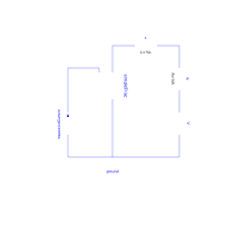
Simple triac test circuit
Extends from Modelica.Icons.Example (Icon for runnable examples).
Information
The simple TRIAC example shows how the SimpleTriac is used within an alternating current circuit.
The TRIAC is not conducting until the Gate input g becomes positive. Then it becomes "conducting". If the TRIAC voltage changes its direction, the TRIAC becomes blocking. Due to the antiparallel connection of the internal two thyristors the same behavior is repeated in the negative half-wave.
Simulate until 0.001 seconds. Display V.p.v (input voltage), simpleTriac.g.i (gate input), and both simplelTriac.n.v and simpleTriac.n.i, which demonstrate the TRIAC behavior.
Components
| Type | Name | Default | Description |
|---|---|---|---|
| Modelica.Electrical.Analog.Basic.Ground | ground | ||
| Modelica.Electrical.Analog.Basic.Inductor | L | ||
| Modelica.Electrical.Analog.Basic.Resistor | R | ||
| Modelica.Electrical.Analog.Sources.SineVoltage | V | ||
| Modelica.Electrical.Analog.Semiconductors.SimpleTriac | simpleTriac | ||
| Sources.TrapezoidCurrent | trapezoidCurrent |
Revisions
- November 25, 2009
by Susann Wolf