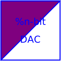
modelDA_Converter

Information
Simple digital to analog converter with a variable input signal width of N bits. The input signal is an N-vector of type Logic (9-valued logic according to IEEE 1164 STD_ULOGIC). The output voltage of value y is generated by an ideal voltage source. The output can only change if the trigger signal trig of type Logic changes to '1' (forced or weak). In this case, the output voltage is calculated in the following way:
     N
y = SUM ( x[i]*2^(i-1) )*Vref/(2^N-1),
    i=1
where x[i], i=1,...,N is 1 or 0. and Vref is the reference value. Therefore, the first bit in the input vector x[1] is the least significant one (LSB) and x[N] is the most significant bit (MSB).
This is an abstract model of a DAC. Hence, it can not cover the dynamic behaviour of the converter. Therefore the output will change instantaneously when the trigger signal rises.
Parameters
| Type | Name | Default | Description |
|---|---|---|---|
| Integer | N | Resolution - input signal width | |
| SI.Voltage | Vref | Reference voltage |
Connectors
| Type | Name | Default | Description |
|---|---|---|---|
| Modelica.Electrical.Digital.Interfaces.DigitalInput | trig | Trigger input | |
| Modelica.Electrical.Digital.Interfaces.DigitalInput[N] | x | Digital input | |
| Modelica.Electrical.Analog.Interfaces.PositivePin | p | Positive electrical pin (output) | |
| Modelica.Electrical.Analog.Interfaces.NegativePin | n | Negative electrical pin (output) |
Components
| Type | Name | Default | Description |
|---|---|---|---|
| SI.Voltage | vout | ||
| Real | y |
Revisions
- October 13, 2009 by Matthias Franke