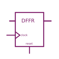
modelDFFR
Edge triggered register bank with reset

Information
Description in VHDL is given by http://www.cs.sfu.ca/~ggbaker/reference/std_logic/src/std_logic_entities
Truth Table for high active reset:
| DataIn | Clock | Reset | DataOut | Map |
| * | * | U | U | 1 |
| * | * | 1 | 0 | 2 |
| * | 0-Trns | 0 | NC | 3 |
| * | 1-Trns | 0 | DataIn | 3 |
| * | X-Trns | 0 | X or U or NC | 3 |
| * | * | X | X or U or 0 or NC | 4 |
Truth Table for low active reset:
| DataIn | Clock | Reset | DataOut | Map |
| * | * | U | U | 1 |
| * | * | 0 | 0 | 2 |
| * | 0-Trns | 1 | NC | 3 |
| * | 1-Trns | 1 | DataIn | 3 |
| * | X-Trns | 1 | X or U or NC | 3 |
| * | * | X | X or U or 0 or NC | 4 |
  *  = do not care
  U  = L.'U'
  0  = L.'0' or L.'L'
  1  = L.'1' or L.'H'
  X  = L.'X' or L.'W' or L.'Z' or L.'-'
  NC = no change

Clock transition definitions:
  1-Trns: 0 -> 1
  0-Trns: ~ -> 0 or 1 -> * or X -> X|U or U -> X|U
  X-Trns: 0 -> X|U or X|U -> 1
Parameters
| Type | Name | Default | Description |
|---|---|---|---|
| Integer[L] | ResetMap | {1, 4, 3, 2, 4, 4, 3, 2, 4} | Function selection, defaults for high active reset |
| D.Interfaces.Strength | strength | S.'S_X01' | Output strength |
| Integer | n | 1 | Data width |
Connectors
| Type | Name | Default | Description |
|---|---|---|---|
| D.Interfaces.DigitalInput | reset | ||
| D.Interfaces.DigitalInput | clock | ||
| D.Interfaces.DigitalInput[n] | dataIn | ||
| D.Interfaces.DigitalOutput[n] | dataOut |
Revisions
- September 11, 2009 created by Ulrich Donath