
modelDimmer_RL
Dimmer with resistive-inductive load
Extends from PowerConverters.Examples.ACAC.ExampleTemplates.Dimmer (Dimmer including control), Modelica.Icons.Example (Icon for runnable examples).
Information
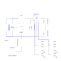
This model demonstrates the behaviour of a dimmer with phase-angle control with resistive-inductive load. Note that due to the inductance the current is not zero at the points in time where zero-crossing of the voltage occurs, and the triac stays conducting until the current becomes zero.
The reference voltage is prescribed by a trapezoid between zero and full voltage. The voltageToAngle block calculates the necessary phase angle, which is processed by the Signal2mPulse adaptor, applying the firing signals to the triac.
Parameters
| Type | Name | Default | Description |
|---|---|---|---|
| SI.Frequency | f (from Dimmer) | 50 | Source frequency |
| SI.Voltage | Vrms (from Dimmer) | 110 | RMS source voltage |
| SI.ApparentPower | S (from Dimmer) | 1000 | Load apparent power |
| Real | powerFactor (from Dimmer) | 0.87 | Load power factor |
| SI.Impedance | ZLoad (from Dimmer) | Vrms^2/S | Load impedance |
| SI.Resistance | RLoad (from Dimmer) | ZLoad*powerFactor | Load resistance |
| SI.Inductance | LLoad (from Dimmer) | ZLoad*sqrt(1 - powerFactor^2)/(2*pi*f) | Load inductance |