
modelDiodeBridge2mPulse
2*m pulse diode rectifier bridge with resistive load
Extends from Modelica.Icons.Example (Icon for runnable examples).
Information
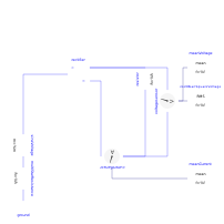
This example shows an uncontrolled 2*m pulse diode bridge rectifier with resistive load, where m is the number of phases.
2*m pulse diode bridge example, where m is the number of phases.
Plot current currentSensor.i, average current meanCurrent.y, voltage voltageSensor.v and average voltage meanVoltage.v.
Parameters
| Type | Name | Default | Description |
|---|---|---|---|
| Integer | m | 3 | Number of phases |
| SI.Voltage | Vrms | 110 | RMS supply voltage |
| SI.Frequency | f | 50 | Frequency |
| SI.Resistance | R | 20 | Load resistance |
Components
| Type | Name | Default | Description |
|---|---|---|---|
| Modelica.Electrical.Polyphase.Sources.SineVoltage | sineVoltage | ||
| PowerConverters.ACDC.DiodeBridge2mPulse | rectifier | ||
| Modelica.Electrical.Analog.Sensors.VoltageSensor | voltagesensor | ||
| Modelica.Blocks.Math.Mean | meanVoltage | ||
| Modelica.Blocks.Math.RootMeanSquare | rootMeanSquareVoltage | ||
| Modelica.Electrical.Analog.Sensors.CurrentSensor | currentSensor | ||
| Modelica.Blocks.Math.Mean | meanCurrent | ||
| Modelica.Electrical.Polyphase.Basic.MultiStarResistance | multiStarResistance | ||
| Modelica.Electrical.Analog.Basic.Ground | ground | ||
| Modelica.Electrical.Analog.Basic.Resistor | resistor |