
modelNand
MOS Nand gate circuit
Extends from Modelica.Icons.Example (Icon for runnable examples).
Information
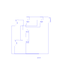
In nearly every electronic the basic circuit "nand" are used. A nand contains two PMOS and two NMOS. The faulty wiring can be seen in the graphical mode. If and only if the two input voltages have high potential, the output voltage has low potential, otherwise the output voltage has high potential.
Nand truth table (1 means true, it is represented by the 5V voltage):
input voltage vin1 |
input voltage vin2 |
output voltage mn1.D |
0 |
0 |
1 |
0 |
1 |
1 |
1 |
0 |
1 |
1 |
1 |
0 |
Simulate until t=2e-7s. Display the two input voltages vin1.p.v and vin2.p.v and the output voltage mn1.D.v, which becomes zero only if both input values are high.
Components
| Type | Name | Default | Description |
|---|---|---|---|
| Semiconductors.M_PMOS | mp1 | ||
| Semiconductors.M_PMOS | mp2 | ||
| Semiconductors.M_NMOS | mn2 | ||
| Semiconductors.M_NMOS | mn1 | ||
| Sources.V_constant | vconstant | ||
| Basic.Ground | ground | ||
| Sources.V_pulse | vin1 | ||
| Sources.V_pulse | vin2 |
Revisions
- May 2009 by Kristin Majetta initially implemented