
classkc_laminar
Extends from Modelica.Icons.Information (Icon for general information packages).
Information
Calculation of mean convective heat transfer coefficient kc of a straight pipe at an uniform wall temperature or uniform heat flux and for a hydrodynamically developed or undeveloped laminar fluid flow.
Functions kc_laminar and kc_laminar_KC
There are basically three differences:
- The function kc_laminar is using kc_laminar_KC but offers additional output variables like e.g. Reynolds number or Nusselt number and failure status (an output of 1 means that the function is not valid for the inputs).
- Generally the function kc_laminar_KC is numerically best used for the calculation of the mean convective heat transfer coefficient kc at known mass flow rate.
- You can perform an inverse calculation from kc_laminar_KC, where an unknown mass flow rate is calculated out of a given mean convective heat transfer coefficient kc
Restriction
- circular cross sectional area
- uniform wall temperature (UWT) or uniform heat flux (UHF)
- hydrodynamically developed fluid flow (DFF) or hydrodynamically undeveloped fluid flow (UFF)
- 0.6 ≤ Prandtl number ≤ 1000
- laminar regime (Reynolds number ≤ 2000)
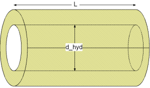
Geometry
Calculation
The mean convective heat transfer coefficient kc of a straight pipe in the laminar regime can be calculated for the following four heat transfer boundary conditions through its corresponding Nusselt number Nu:
Uniform wall temperature in developed fluid flow (heatTransferBoundary == Modelica.Fluid.Dissipation.Utilities.Types.HeatTransferBoundary.UWTuDFF) according to [VDI 2002, p. Ga 2, eq. 6] :
Nu_TD = [3.66^3 + 0.7^3 + {1.615*(Re*Pr*d_hyd/L)^1/3 - 0.7}^3]^1/3
Uniform heat flux in developed fluid flow (heatTransferBoundary == Modelica.Fluid.Dissipation.Utilities.Types.HeatTransferBoundary.UHFuDFF) according to [VDI 2002, p. Ga 4, eq. 19] :
Nu_qD = [4.364^3 + 0.6^3 + {1.953*(Re*Pr*d_hyd/L)^1/3 - 0.6}^3]^1/3
Uniform wall temperature in undeveloped fluid flow (heatTransferBoundary == Modelica.Fluid.Dissipation.Utilities.Types.HeatTransferBoundary.UWTuUFF) according to [VDI 2002, p. Ga 2, eq. 12] :
Nu_TU = [3.66^3 + 0.7^3 + {1.615*(Re*Pr*d_hyd/L)^1/3 - 0.7}^3 + {(2/[1+22*Pr])^1/6*(Re*Pr*d_hyd/L)^0.5}^3]^1/3
Uniform heat flux in developed fluid flow (heatTransferBoundary == Modelica.Fluid.Dissipation.Utilities.Types.HeatTransferBoundary.UHFuUFF) according to [VDI 2002, p. Ga 5, eq. 25] :
Nu_qU = [4.364^3 + 0.6^3 + {1.953*(Re*Pr*d_hyd/L)^1/3 - 0.6}^3 + {0.924*Pr^1/3*[Re*d_hyd/L]^0.5}^3]^1/3.
The corresponding mean convective heat transfer coefficient kc is determined w.r.t. the chosen heat transfer boundary by:
kc = Nu * lambda / d_hyd
with
| d_hyd | as hydraulic diameter of straight pipe [m], |
| kc | as mean convective heat transfer coefficient [W/(m2K)], |
| lambda | as heat conductivity of fluid [W/(mK)], |
| L | as length of straight pipe [m], |
| Nu = kc*d_hyd/lambda | as mean Nusselt number [-], |
| Pr = eta*cp/lambda | as Prandtl number [-], |
| Re = rho*v*d_hyd/eta | as Reynolds number [-], |
| v | as mean velocity [m/s]. |
Verification
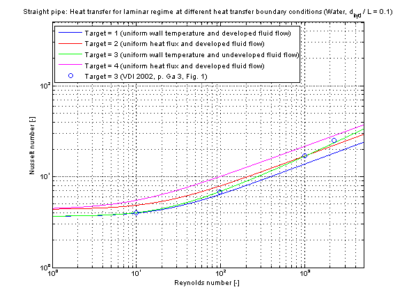
The mean Nusselt number Nu representing the mean convective heat transfer coefficient kc depending on four different heat transfer boundary conditions is shown in the figures below.
This verification has been done with the fluid properties of Water (Prandtl number Pr = 7) and a diameter to pipe length fraction of 0.1.
References
- Bejan,A.:
- Heat transfer handbook. Wiley, 2003.
- VDI:
- VDI - Wärmeatlas: Berechnungsblätter für den Wärmeübergang. Springer Verlag, 9th edition, 2002.