
classdp_severalGeometryOverall
Extends from Modelica.Icons.Information (Icon for general information packages).
Information
Calculation of pressure loss for a valve with different geometries at overall flow regime for incompressible and single-phase fluid flow in dependence of its opening.
Restriction
This function shall be used inside of the restricted limits according to the referenced literature.
- developed fluid flow
- ball valve
- diaphragm valve
- butterfly valve
- gate valve
- sluice valve
Geometry
Wide variations in valve geometry are possible and a manufacturer will not necessarily maintain geometric similarity between valves of the same type but of different size. Here pressure loss can be estimated for the following types of a valve:
- ball valve
- diaphragm valve
- butterfly valve
- gate valve
- sluice valve
Calculation
The mass flow rate m_flow for valves out of pressure loss is determined by:
m_flow = [rho * dp * Av^2 / (zeta_TOT/2]^0.5
m_flow = (2/zeta_TOT)^0.5 * Av * (rho * dp)^0.5
m_flow = valveCharacteristic * Av * (rho * dp)^0.5
with
| rho | as density of fluid [kg/m3], |
| Av | as (metric) flow coefficient (cross sectional area) [m^2], |
| m_flow | as mass flow rate [kg/s], |
| valveCharacteristic | as coefficient of a valve in dependence of its opening [-], |
| velocity | as mean velocity [m/s], |
| zeta_TOT | as pressure loss coefficient [-]. |
The valveCharacteristic is determined out of a correlation for the pressure loss coefficient (zeta_TOT) in dependence of its opening. The reason for introducing an additional variable valveCharacteristic is a different definition of the following pressure loss correlations of valves.
Verification
The pressure loss coefficient (zeta_TOT) of a valve with different geometries are shown in dependence of the opening in the figure below.
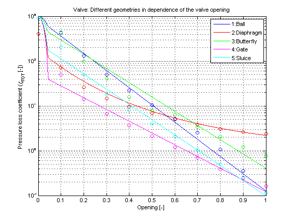
Note that the pressure loss coefficients (zeta_TOT) are numerically optimized for very small openings (opening ≤ 5%). At openings smaller than 5% the pressure loss coefficient is smoothly set to a maximum value (zeta_TOT_max) to be adjusted as parameter. Therefore a very small leakage mass flow rate can be adjusted for a given pressure difference at almost closed valves. A very small leakage mass flow rate can often be neglected in system simulation with valves, whereas the numerical behaviour of the simulation is improved.
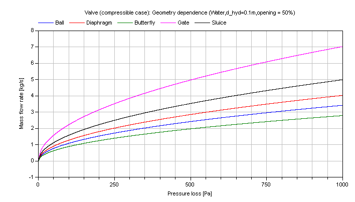
The mass flow rate of different valves at a constant opening of 50% in dependence of pressure loss is shown in the figure below.
References
- Miller,D.S.:
- Internal flow systems. Volume 5th of BHRA Fluid Engineering Series. BHRA Fluid Engineering, 1978.