
modelPermeanceActuator
Information
In the ConstantActuator model the force F is strictly proportional to the current i as indicated by the converter constant c. However, there is an additional non-linear force component in such an actuator that is due to the dependency of the coil inductance L on the armature position x. The inductance increases as the armature moves into the stator. The total force is
    1  2 dL
F = - i  --  + c i
    2    dx
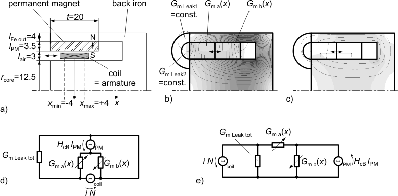
Both force components are properly considered with a simple permeance model as shown in the figures below. Figure (a) illustrates the dimensions of the axis-symmetric moving coil actuator that are needed in the permeance model. Figure (b) shows partitioning into flux tubes and the permanent magnetic field without current. G_ma and G_mb both are the permeances resulting from a series connection of the permanent magnet and air gap sections. The field plot of the coil-imposed mmf is shown in figure (c) without the permanent magnetic mmf (H_cB=0). The placement of the magnetic network components in figure (d) retains the geometric structure of the actuator. In figure (e), the permeance model is restructured and thus simplified.
Parameters
| Type | Name | Default | Description |
|---|---|---|---|
| SI.Resistance | R | 2.86 | Coil resistance |
| SI.Radius | r_core | 12.5e-3 | Radius of ferromagnetic stator core |
| SI.Length | l_PM | 3.5e-3 | Radial thickness of permanent magnet ring |
| SI.Length | t | 0.02 | Axial length of permanent magnet ring and air gap respectively |
| SI.Length | l_air | 3e-3 | Total radial length of armature air gap |
| SI.Length | l_FeOut | 4e-3 | Radial thickness of outer back iron (for estimation of leakage permeance) |
| Parameters | |||
| Real | N | 140 | Number of turns |
| Material | |||
| FluxTubes.Material.HardMagnetic.BaseData | material | Material.HardMagnetic.BaseData() | Ferromagnetic material characteristics |
| Armature and stopper | |||
| SI.Mass | m_a | 0.012 | Mass of armature |
| SI.TranslationalSpringConstant | c | 1e11 | Spring stiffness between impact partners |
| SI.TranslationalDampingConstant | d | 400 | Damping coefficient between impact partners |
| SI.Position | x_min | -4e-3 | Position of stopper at minimum armature position |
| SI.Position | x_max | 4e-3 | Position of stopper at maximum armature position |
Connectors
| Type | Name | Default | Description |
|---|---|---|---|
| Modelica.Electrical.Analog.Interfaces.PositivePin | p | Electrical connector | |
| Modelica.Electrical.Analog.Interfaces.NegativePin | n | Electrical connector | |
| Modelica.Mechanics.Translational.Interfaces.Flange_b | flange | Flange of component |
Components
| Type | Name | Default | Description |
|---|---|---|---|
| SI.Position | x | Armature position, alias for flange position | |
| SI.Inductance | L | Coil inductance | |
| FluxTubes.Sources.ConstantMagneticPotentialDifference | mmf_PM | Permanent magnet's magnetomotive force | |
| FluxTubes.Examples.Utilities.TranslatoryArmatureAndStopper | armature | Inertia of moving coil + coil carrier; stoppers at end of stroke range | |
| Modelica.Electrical.Analog.Basic.Resistor | r | ||
| Basic.Ground | ground | ||
| FluxTubes.Basic.ElectroMagneticConverter | coil | ||
| FluxTubes.Shapes.Force.HollowCylinderRadialFlux | g_ma | ||
| FluxTubes.Shapes.Force.HollowCylinderRadialFlux | g_mb | ||
| FluxTubes.Shapes.Leakage.CoaxCylindersEndFaces | g_mLeak1 | Leakage between coaxial end planes of ferromagnetic stator core and outer back iron | |
| FluxTubes.Shapes.Leakage.HalfCylinder | g_mLeak2 | Leakage between edges of ferromagnetic stator core and outer back iron |