
modelAdvancedSolenoid
Advanced network model of a lifting magnet with planar armature end face, split magnetomotive force
Information
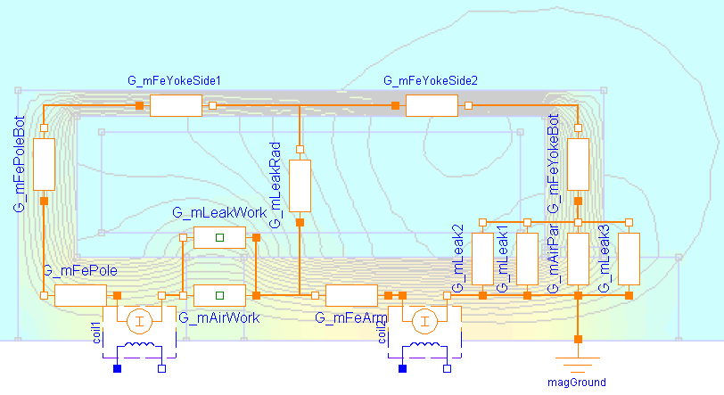
Please have a look at SimpleSolenoid for a general description of this actuator. Unlike in that simple magnetic network model, the coil is split into two lumped elements here. This enables for more realistic modelling of the radial leakage flux between armature and yoke (leakage permeance G_mLeakRad). Especially for large air gaps, the influence of this leakage flux on the actuator's inductance and its electromagnetic force is rather strong. Please have a look at ComparisonQuasiStatic for a comparison of both models with FEA-based results included as reference.
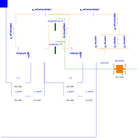
The parasitic capacitances c_par1 and c_par2 across both partial coils assure that the voltages across these coils are well-defined during simulation.
Parameters
| Type | Name | Default | Description |
|---|---|---|---|
| SI.Resistance | R | 5 | Coil resistance |
| SI.Resistance | R_par | 1e5 | Resistance parallel to the coil, in series to C_par |
| SI.Capacitance | C_par | 1e-9 | Capacitance parallel to the coil, in series to R_par |
| SI.Radius | r_yokeOut | 15e-3 | Outer yoke radius |
| SI.Radius | r_yokeIn | 13.5e-3 | Inner yoke radius |
| SI.Length | l_yoke | 35e-3 | Axial yoke length |
| SI.Length | t_yokeBot | 3.5e-3 | Axial thickness of yoke bottom |
| SI.Length | l_pole | 6.5e-3 | Axial length of pole |
| SI.Length | t_poleBot | 3.5e-3 | Axial thickness of bottom at pole side |
| SI.Length | t_airPar | 0.65e-3 | Radial thickness of parasitic air gap due to slide guiding |
| Parameters | |||
| Real | N | 957 | Number of turns |
| Material | |||
| FluxTubes.Material.SoftMagnetic.BaseData | material | Material.SoftMagnetic.Steel.Steel_9SMnPb28() | Ferromagnetic material characteristics |
| Armature and stopper | |||
| SI.Radius | r_arm | 5e-3 | Armature radius = pole radius |
| SI.Length | l_arm | 26e-3 | Armature length |
| SI.TranslationalSpringConstant | c | 1e11 | Spring stiffness between impact partners |
| SI.TranslationalDampingConstant | d | 400 | Damping coefficient between impact partners |
| SI.Position | x_min | 0.25e-3 | Stopper at minimum armature position |
| SI.Position | x_max | 5e-3 | Stopper at maximum armature position |
Connectors
| Type | Name | Default | Description |
|---|---|---|---|
| Modelica.Electrical.Analog.Interfaces.PositivePin | p | Electrical connector | |
| Modelica.Electrical.Analog.Interfaces.NegativePin | n | Electrical connector | |
| Modelica.Mechanics.Translational.Interfaces.Flange_b | flange | Flange of component |
Components
| Type | Name | Default | Description |
|---|---|---|---|
| SI.Position | x | Armature position | |
| SI.MagneticFlux | Psi_tot | Total flux linkage for information only | |
| SI.Inductance | L_statTot | Total static inductance for information only | |
| FluxTubes.Basic.Ground | ground | ||
| FluxTubes.Basic.ElectroMagneticConverter | coil1 | Electromagnetic conversion in first half of coil | |
| Modelica.Electrical.Analog.Basic.Resistor | r_1 | Resistance of first half of coil | |
| FluxTubes.Shapes.FixedShape.HollowCylinderAxialFlux | g_mFeYokeSide1 | Permeance of first half of yoke's hollow cylindric section | |
| FluxTubes.Shapes.FixedShape.HollowCylinderAxialFlux | g_mFeArm | Permeance of ferromagnetic armature | |
| FluxTubes.Shapes.Force.HollowCylinderAxialFlux | g_mAirWork | Permeance of working air gap (between armature and pole end faces) | |
| FluxTubes.Shapes.FixedShape.HollowCylinderRadialFlux | g_mFeYokeBot | Permeance of bottom side of ferromagnetic yoke | |
| FluxTubes.Shapes.FixedShape.HollowCylinderRadialFlux | g_mAirPar | Permeance of parasitic radial air gap due to slide guiding | |
| FluxTubes.Shapes.FixedShape.HollowCylinderRadialFlux | g_mFePoleBot | Permeance of bottom side of pole | |
| FluxTubes.Shapes.FixedShape.HollowCylinderAxialFlux | g_mFePole | Permeance of ferromagnetic pole | |
| FluxTubes.Examples.Utilities.TranslatoryArmatureAndStopper | armature | Inertia of armature and stoppers at end of stroke range | |
| FluxTubes.Shapes.Leakage.QuarterCylinder | g_mLeak1 | Leakage permeance between inner edge of yoke bore and armature side face | |
| FluxTubes.Shapes.Leakage.QuarterHollowCylinder | g_mLeak2 | Leakage permeance between inner side of yoke bottom and armature side (r_i = t_airPar) | |
| FluxTubes.Basic.ElectroMagneticConverter | coil2 | Electromagnetic conversion in first half of coil | |
| Modelica.Electrical.Analog.Basic.Capacitor | c_par1 | Parasitic capacitance assigned to first half of coil | |
| FluxTubes.Shapes.FixedShape.HollowCylinderRadialFlux | G_mLeakRad | Permeance of radial leakage flux tube between armature side and yoke side | |
| FluxTubes.Shapes.FixedShape.HollowCylinderAxialFlux | g_mFeYokeSide2 | Permeance of second half of yoke's hollow cylindric section | |
| Modelica.Electrical.Analog.Basic.Capacitor | c_par2 | Parasitic capacitance assigned to second half of coil | |
| Modelica.Electrical.Analog.Basic.Resistor | r_par1 | Parasitic resistance assigned to first half of coil | |
| Modelica.Electrical.Analog.Basic.Resistor | r_par2 | Parasitic resistance assigned to second half of coil | |
| Modelica.Electrical.Analog.Basic.Resistor | r_2 | Resistance of second half of coil | |
| FluxTubes.Shapes.Leakage.QuarterCylinder | g_mLeak3 | Leakage permeance between outer edge of yoke bore and armature side face | |
| FluxTubes.Shapes.Force.LeakageAroundPoles | g_mLeakWork | Permeance of leakage air gap around working air gap (between armature and pole side faces) |