
modelQuadraticCoreAirgap
Extends from Modelica.Icons.Example (Icon for runnable examples).
Information
Educational example of a magnetic circuit containing an iron core and an airgap:
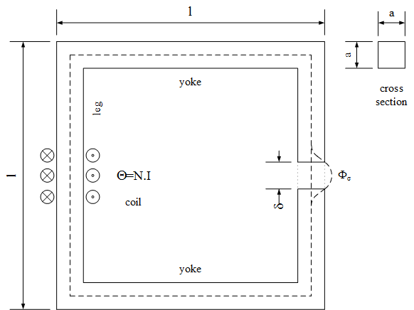
A current ramp is applied in positive electric direction through the exciting coil, causing a rising magnetomotive force (mmf) in positive magnetic direction of the electromagnetic converter. The mmf in turn causes a magnetic flux through the circuit in the direction indicated by the flux sensor. From that magnetic flux, flux density can be calculated in every element of the magnetic circuit. Flux density is used to derive magnetic field strength. Magnetic field strength times length of the flux line gives magnetic potential difference of each element. The sum of all magnetic potential differences is covered by the mmf of the exciting coil.
Using the parameter values, the results can be validated by analytic calculations:
| element | cross section | length | rel. permeability | B | H | mmf |
|---|---|---|---|---|---|---|
| left leg | a*a | l - a | μr | flux / cross section | B/(μr*μ0) | H*length |
| upper yoke | a*a | l - a | μr | flux / cross section | B/(μr*μ0) | H*length |
| right leg | a*a | l - a - delta | μr | flux / cross section | B/(μr*μ0) | H*length |
| airgap | a*a | delta | 1 | useful flux / cross section | B/μ0 | H*length |
| lower yoke | a*a | l - a | μr | flux / cross section | B/(μr*μ0) | H*length |
| total | Σ mmf = N*I |
Note that there is a leakage flux path present. Therefore the total magnetic flux of in core splits into
- the useful flux through the airgap and
- the leakage flux through the leakage element.
However, the magnetic voltage across the airgap and the leakage model are equal.
The ratio of the useful flux over the flux in the core is equal to 1 - σ.
In the core the magnetic flux is the same in every element as they are connected in series.
For the calculation of the length of flux lines inside the core, a medium flux line (dashed line) is used
Additionally, a measuring coil is placed in the airgap. Due to Faraday's law, the time derivative of flux causes an induced voltage both in the exciting coil (in positive direction) and in the measuring coil (in negative direction). Since the quasi static current and therefore flux follow a time dependent ramp, the quasi static induced voltages follow a ramp as well.
Note the proper usage of electric and magnetic grounds to define zero potential.
Parameters
| Type | Name | Default | Description |
|---|---|---|---|
| SI.Length | l | 0.1 | Outer length of iron core |
| SI.Length | a | 0.01 | Side length of square cross section |
| Real | mu_r | 1000 | Relative permeability of core |
| SI.Length | delta | 0.001 | Length of airgap |
| Real | sigma | 0.1 | Leakage coefficient |
| Integer | N | 500 | Number of turns of exciting coil |
| SI.Current | I | 1.5 | Maximum exciting current |