
modelHalfControlledBridge2mPulse
2*m pulse half controlled rectifier bridge with resistive load
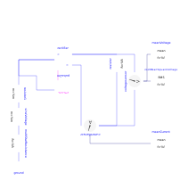
Extends from Modelica.Icons.Example (Icon for runnable examples).
Information
This example shows a half controlled 2*m pulse bridge rectifier with resistive load, where m is the number of phases. In case of resistive load the half controlled bridge shows the same output voltage as the
full controlled bridge.
Plot current currentSensor.i, average current meanCurrent.y, voltage voltageSensor.v and average voltage meanVoltage.v.
Parameters
| Type | Name | Default | Description |
|---|---|---|---|
| Integer | m | 3 | Number of phases |
| SI.Voltage | Vrms | 110 | RMS supply voltage |
| SI.Frequency | f | 50 | Frequency |
| SI.Angle | constantFiringAngle | 30*pi/180 | Firing angle |
| SI.Resistance | R | 20 | Load resistance |
Components
| Type | Name | Default | Description |
|---|---|---|---|
| Modelica.Electrical.Polyphase.Sources.SineVoltage | sineVoltage | ||
| Modelica_Electrical_PowerConverters.ACDC.HalfControlledBridge2mPulse | rectifier | ||
| Modelica.Electrical.Analog.Sensors.VoltageSensor | voltagesensor | ||
| Modelica.Blocks.Math.Mean | meanVoltage | ||
| Modelica.Blocks.Math.RootMeanSquare | rootMeanSquareVoltage | ||
| Modelica.Electrical.Analog.Sensors.CurrentSensor | currentSensor | ||
| Modelica.Blocks.Math.Mean | meanCurrent | ||
| Modelica_Electrical_PowerConverters.ACDC.Control.VoltageBridge2mPulse | pulse2m | ||
| Modelica.Electrical.Polyphase.Basic.MultiStarResistance | multiStarResistance | ||
| Modelica.Electrical.Analog.Basic.Ground | ground | ||
| Modelica.Electrical.Analog.Basic.Resistor | resistor | ||
| Modelica.Electrical.Polyphase.Basic.Resistor | resistor1 |