functionstep
Step response plot
Extends from Modelica_LinearSystems2.Internal.PartialPlotFunctionMIMO (Interface of a plot function for MIMO systems).
Information
Syntax
StateSpace.Plot.step(ss);
   or
StateSpace.Plot.step(
  ss,
  dt,
  tSpan,
  x0,
  defaultDiagram=Modelica_LinearSystems2.Internal.DefaultDiagramTimeResponse(),
  device=Modelica_LinearSystems2.Utilities.Plot.Records.Device())
Description
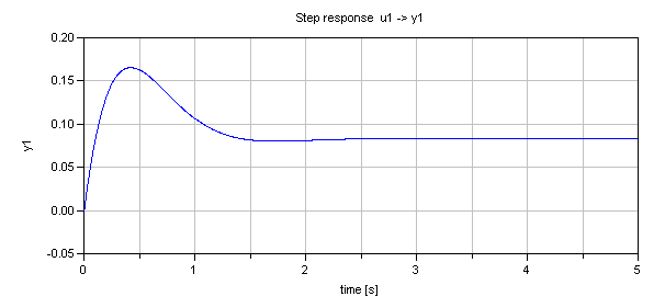
This function plots the step responses of a state space system for each system corresponding to the transition matrix. It is based on timeResponse.
Example
  Modelica_LinearSystems2.StateSpace ss=Modelica_LinearSystems2.StateSpace(
    A=[-1.0,0.0,0.0; 0.0,-2.0,3.0; 0.0,-2.0,-3.0],
    B=[1.0; 1.0; 0.0],
    C=[0.0,1.0,1.0],
    D=[0.0])

algorithm
  Modelica_LinearSystems2.StateSpace.Plot.step(ss, tSpan=3)
// gives:
See also
Inputs
| Type | Name | Default | Description |
|---|---|---|---|
| StateSpace | ss | State space system | |
| Modelica.Units.SI.Time | dt | 0 | Sample time |
| Modelica.Units.SI.Time | tSpan | 0 | Simulation time span |
| Real[size(ss.A, 1)] | x0 | zeros(size(ss.A, 1)) | Initial state vector |
| Boolean | subPlots | true | True, if all subsystem time responses are plotted in one window with subplots |
| Plot.Records.Diagram | defaultDiagram (from PartialPlotFunctionMIMO) | Default diagram layout | |
| Plot.Records.Device | device (from PartialPlotFunctionMIMO) | Modelica_LinearSystems2.Utilities.Plot.Records.Device() | Properties of device where figure is shown |
| TimeResponse | response | TimeResponse.Step | type of time response |