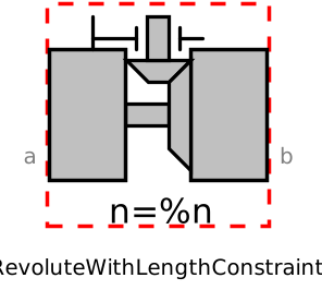
modelRevoluteWithLengthConstraint
Extends from Modelica.Mechanics.MultiBody.Interfaces.PartialTwoFrames (Base model for components providing two frame connectors + outer world + assert to guarantee that the component is connected), ObsoleteModelica3.Icons.ObsoleteModel (Icon for an obsolete model (use only for this case)).
Information
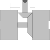
Joint where frame_b rotates around axis n which is fixed in frame_a. The two frames coincide when "phi + phi_offset = 0", where "phi_offset" is a parameter with a zero default and "phi" is the rotation angle.
This variant of the revolute joint is designed to work together with a length constraint in a kinematic loop. This means that the angle of the revolute joint, phi, is computed such that the length constraint is fulfilled.
Usually, this joint should not be used by a user of the MultiBody library. It is only provided to built-up the Modelica.Mechanics.MultiBody.Joints.Assemblies.JointXYZ joints.
Parameters
| Type | Name | Default | Description |
|---|---|---|---|
| Boolean | animation | true | = true, if animation shall be enabled |
| SI.Position | lengthConstraint | 1 | Fixed length of length constraint |
| Modelica.Mechanics.MultiBody.Types.Axis | n | {0, 0, 1} | Axis of rotation resolved in frame_a (= same as in frame_b) |
| Cv.NonSIunits.Angle_deg | phi_offset | 0 | Relative angle offset (angle = phi + from_deg(phi_offset)) |
| Cv.NonSIunits.Angle_deg | phi_guess | 0 | Select the configuration such that at initial time |phi - from_deg(phi_guess)|is minimal |
| Boolean | positiveBranch | Based on phi_guess, selection of one of the two solutions of the non-linear constraint equation | |
| Real[3] | e | Modelica.Math.Vectors.normalize(n) | Unit vector in direction of rotation axis, resolved in frame_a |
| Animation › if animation = true | |||
| SI.Distance | cylinderLength | world.defaultJointLength | Length of cylinder representing the joint axis |
| SI.Distance | cylinderDiameter | world.defaultJointWidth | Diameter of cylinder representing the joint axis |
| Advanced | |||
| Boolean | axisTorqueBalance | true | = true, if torque balance of flange axis with the frame_b connector (axis.tau = -e*frame_b.t) shall be defined. Otherwise this equation has to be provided outside of this joint |
Connectors
| Type | Name | Default | Description |
|---|---|---|---|
| Interfaces.Frame_a | frame_a (from PartialTwoFrames) | Coordinate system a fixed to the component with one cut-force and cut-torque | |
| Interfaces.Frame_b | frame_b (from PartialTwoFrames) | Coordinate system b fixed to the component with one cut-force and cut-torque | |
| Modelica.Mechanics.Rotational.Interfaces.Flange_a | axis | 1-dim. rotational flange that drives the joint | |
| Modelica.Mechanics.Rotational.Interfaces.Flange_b | bearing | 1-dim. rotational flange of the drive bearing | |
| Modelica.Blocks.Interfaces.RealInput[3] | position_a | Position vector from frame_a to frame_a side of length constraint, resolved in frame_a of revolute joint | |
| Modelica.Blocks.Interfaces.RealInput[3] | position_b | Position vector from frame_b to frame_b side of length constraint, resolved in frame_b of revolute joint |
Components
| Type | Name | Default | Description |
|---|---|---|---|
| Modelica.Mechanics.MultiBody.Types.Color | cylinderColor | Modelica.Mechanics.MultiBody.Types.Defaults.JointColor | Color of cylinder representing the joint axis |
| Modelica.Mechanics.MultiBody.Types.SpecularCoefficient | specularCoefficient | world.defaultSpecularCoefficient | Reflection of ambient light (= 0: light is completely absorbed) |
| SI.Angle | phi | Rotation angle of revolute joint | |
| Modelica.Mechanics.MultiBody.Frames.Orientation | R_rel | Relative orientation object from frame_a to frame_b | |
| SI.Angle | angle | = phi + from_deg(phi_offset) (relative rotation angle between frame_a and frame_b) | |
| SI.Torque | tau | = axis.tau (driving torque in the axis) |
Contents
| Name | Description |
|---|---|
| selectBranchprotected | Determine branch which is closest to initial angle=0 |