
modelMotorComparisonLDQ

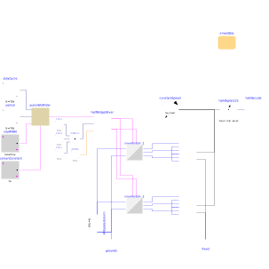
Test setup to compare the effect of different L_q and L_d
Extends from Modelica.Icons.Example (Icon for runnable examples).

Information

This model is used to compare the stator frame PMSM model with the model from the MSL.

The connectors a and b are operated in 2-leg PWM mode. Observe the voltage on the open connector c of inverter3ph_2 and the torque of the motor.

Parameters

TypeNameDefaultDescription
Integerm3Number of phases
Integerppz6Motor pairs of poles
Modelica.SIunits.ResistanceR_p0.33/2Motor per phase resistance
Modelica.SIunits.InductanceL_p3.5e-5/2Motor per phase inductance
Realm_k0.9Mutual coupling coefficient
Modelica.SIunits.DurationT_PWM50e-6
Modelica.Electrical.Machines.Utilities.SynchronousMachineDatasmeeData

Components

TypeNameDefaultDescription
Sensors.HallDigital123hallDigital123
Modelica.Mechanics.Rotational.Sources.ConstantSpeedconstantSpeed
Modelica.Mechanics.Rotational.Components.Fixedfixed
Blocks.HallDecodehallDecode
Modelica.Electrical.Analog.Basic.Groundground1
Machines.PMSMmpMSM_run
Machines.SM_PermanentMagnet_WRPsM_PermanentMagnet_WRP1
Modelica.Electrical.Analog.Sources.ConstantVoltageconstantVoltage
Converters.SwitchingIdeal.Inverter3phinverter3ph_1
Converters.SwitchingIdeal.Inverter3phinverter3ph_2
Blocks.PulseWidthVar[3]pulseWidthVar
Blocks.HalfBridgeLogicBLDC[3]halfBridgeDriver
Modelica.Blocks.Sources.BooleanStep[3]startPWM
Modelica.Blocks.Sources.BooleanConstant[3]booleanConstant
Modelica.Blocks.Sources.Constant[3]periodPWM period
Modelica.Blocks.Sources.Constant[3]dutyCyclePWM duty cycle
Modelica.Blocks.Sources.Constantmode_aFixed bridge mode
Modelica.Blocks.Routing.Multiplex3multiplex3_1
Modelica.Blocks.Sources.Constantmode_bFixed bridge mode
Modelica.Blocks.Sources.Constantmode_cFixed bridge mode
Modelica.Blocks.Sources.IntegerConstant[3]pwmMode