modelFrancis

Extends from Icons.Turbine (Turbine icon), OpenHPL.Interfaces.TwoContacts (Model of two connectors), OpenHPL.Interfaces.TurbineContacts (Model of turbine connectors).
Information
Francis Turbine Model
This is the Francis turbine model that gives possibilities for proper modelling of the Francis turbine. The mechanistic model is based on Euler equations for the Francis turbine.
Besides hydraulic input and output, there are input as the control signal for the valve opening and also output as the turbine shaft power and input as angular velocity.
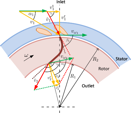
Figure: Key quantities in the Francis turbine model showing inlet (1) and outlet (2) sections.
Euler Turbine Equations
The shaft power produced by the turbine is given by:
$$ \dot{W}_s = \dot{m}\omega \left(R_1\frac{\dot{V}}{A_1}\cot{\alpha_1} - R_2\left(\omega R_2 + \frac{\dot{V}}{A_2}\cot{\beta_2}\right)\right) $$
where ṁ and V̇ are mass and volumetric flow rates, ω is angular velocity, R1 and R2 are inlet and outlet radii, A1 and A2 are cross-sectional areas, α1 is inlet guide vane angle, and β2 is outlet blade angle.
Total Work and Efficiency
The total work rate is:
$$ \dot{W}_t = \dot{W}_s + \dot{W}_{ft} + \Delta p_v \dot{V} $$
where Ẇft represents various friction losses (shock, whirl, wall friction), and ΔpvV̇ accounts for guide vane pressure drop. Turbine efficiency \(\eta = \dot{W}_s / \dot{W}_t\).
Turbine Design Algorithm
There is also available the runner design algorithm that can define all geometrical parameters based on the nominal parameters (net head, flow rate, power, speed). The algorithm determines: outlet blade angle β2, runner radii R1 and R2, runner width w1, and inlet blade angle β1.
The turbine losses coefficients (k_ft1, k_ft2, k_ft3) can be also
defined automatically. However, if some dynamic data from real turbine is available it is better to tune
these parameters a bit more and use the defined values as a starting point.
Guide Vane Actuation
A model for servo that runs the guide vane opening is also available. A guide vane opening model relates actuator position Y to guide vane angle α1 through geometric relationships. Furthermore it is possible to automatically generate all needed parameters for the servo, or simply specify them.
Low Load Performance
This mechanistic turbine model does not work really well for low loads (<10% guide vane opening).
However there is parameters that could be tuned for low load regimes.
These are u_min and k_ft4.
More Information
More info about the mechanistic turbine model can be found in: [Vytvytskyi2018] and [Vytvytskyi2019]. Additional details about the servo (and turbine model) are in: Resources/Documents/Turbines_model.pdf.
Parameters
| Type | Name | Default | Description |
|---|---|---|---|
| Given data | |||
| Boolean | GivenData | true | If checked the user specifies whole set of parameters. Otherwise, the design algorithm will be used for missed parameters |
| Guide vane | |||
| Boolean | dp_v_condition | false | If checked then it includes the pressure drop through the guide vane (leave it unchecked - this doesn't work well) |
| SI.Radius | R_v_ | 2.89/2 | Radius of the guide vane suspension circle |
| SI.Length | w_v_ | w_1_ | Width of the guide vane suspension circle |
| Real | k_fv | 0 | Friction loss coefficient from turbine entrance and across guide vanes |
| Real | Reduction | 0.2 | Reduction the given formula for the guide vane pressure drop |
| Servo | |||
| Boolean | GivenServoData | true | If checked the user specifies parameters for the servo. Otherwise, the design algorithm will be used for missed parameters |
| SI.Length | r_v_ | 1.1 | Radius of servo circle |
| SI.Length | r_Y_ | 1.2 | Radius to servo connection |
| SI.Length | R_Y_ | 3 | Radius to servo |
| Real | u_start_ | 2.28 | Servo position with zero flow |
| Real | u_end_ | 2.4 | Servo position with full flow |
| Nominal parameters | |||
| SI.Height | H_n | 460 | Nominal head |
| SI.VolumeFlowRate | Vdot_n | 24.3 | Nominal flow |
| SI.Power | P_n | 103e6 | Nominal power |
| Modelica.Units.NonSI.AngularVelocity_rpm | n_n | 500 | Nominal turbine speed |
| Runner | |||
| SI.Radius | R_1_ | 2.63/2 | Radius of the turbine blade inlet |
| SI.Radius | R_2_ | 1.55/2 | Radius of the turbine blade outlet |
| SI.Length | w_1_ | 0.2 | Width of the turbine/blades inlet |
| Modelica.Units.NonSI.Angle_deg | beta1_ | 110 | Turbine inlet blade angle |
| Modelica.Units.NonSI.Angle_deg | beta2_ | 162.5 | Turbine outlet blade angle |
| Guide vane › Scroll case | |||
| SI.Diameter | D_i | 1.632 | Diameter of the inlet pipe |
| Losses in runner | |||
| Boolean | Given_losses | true | Friction shock loss coefficient due to shock |
| Real | k_ft1_ | 7e5 | Friction shock loss coefficient due to shock |
| Real | k_ft2_ | 0 | Hydraulic friction loss coefficient due to effluent whirl |
| Real | k_ft3_ | 1.63e4 | Friction loss coefficient due to wall friction |
| Parameters for low load | |||
| Real | k_ft4 | k_ft3_*100 | Friction loss coefficient that is used for low load (under u_min) |
| Real | u_min | 0.03 | Control signal value under which the moodel used k_f4 friction term to balance the model |
| Condition | |||
| Boolean | WaterCompress | false | If checked the water is compressible in the penstock |
| I/O › Outputs | |||
| Boolean | enable_P_out (from TurbineContacts) | false | If checked, get a connector for the output power |
Connectors
| Type | Name | Default | Description |
|---|---|---|---|
| Contact_i | i (from TwoContacts) | Inlet contact (positive design flow direction is from i to o) | |
| Contact_o | o (from TwoContacts) | Outlet contact (positive design flow direction is from i to o) | |
| Modelica.Blocks.Interfaces.RealInput | u_t (from TurbineContacts) | [Guide vane|nozzle] opening of the turbine(=1: completely open, =0: completely closed) | |
| Modelica.Blocks.Interfaces.RealOutput | P_out (from TurbineContacts) | Mechanical Output power | |
| Modelica.Blocks.Interfaces.RealInput | w_in | Input angular velocity from the generator |
Components
| Type | Name | Default | Description |
|---|---|---|---|
| Data | data | Using standard class with constants | |
| SI.Pressure | p_r1 | Runner inlet pressure | |
| SI.Pressure | dp_tr | Turbine pressure drop | |
| SI.Pressure | dp_r | Runner pressure drop | |
| SI.Pressure | p_tr2 | Turbine outlet pressure | |
| SI.Pressure | dp_v | Guide vane pressure drop | |
| SI.Area | A_1 | Runner inlet cross section | |
| SI.Area | A_0 | Turbine inlet cross section | |
| SI.Area | A_v | Guide vane cross section | |
| SI.Area | A_2 | Runner outlet cross section | |
| SI.EnergyFlowRate | Wdot_s | Shaft power | |
| SI.EnergyFlowRate | Wdot_ft | Total runner losses | |
| SI.EnergyFlowRate | W_t1 | Euler first term | |
| SI.EnergyFlowRate | W_t2 | Euler second term | |
| SI.EnergyFlowRate | Wdot_ft_s | Shock losses | |
| SI.EnergyFlowRate | Wdot_ft_w | Whirl losses | |
| SI.EnergyFlowRate | Wdot_ft_l | Friction losses | |
| SI.EnergyFlowRate | Wdot_t | Total power | |
| SI.VolumeFlowRate | Vdot | Flow rate | |
| SI.MassFlowRate | mdot | Mass flow rate | |
| SI.AngularVelocity | w | w_in | Angular velocity |
| SI.Velocity | u_2 | Outlet reference velocity | |
| SI.Velocity | c_m2 | Outlet meridional velocity | |
| SI.Velocity | c_m1 | Inlet meridional velocity | |
| SI.Velocity | u_1 | Inlet reference velocity | |
| SI.Velocity | c_u1 | Inlet tangential velocity | |
| Modelica.Units.NonSI.Angle_deg | beta1 | Inlet blade angle | |
| Modelica.Units.NonSI.Angle_deg | beta2 | Outlet blade angle | |
| Modelica.Units.NonSI.Angle_deg | _beta1 | ||
| SI.Angle | alpha1 | Inlet guide vane angle | |
| SI.Angle | phi | One of servo angles | |
| SI.Angle | psi | One of servo angles | |
| SI.Angle | theta | One of servo angles | |
| SI.Angle | dtheta | One of servo angles | |
| Real | k_ft1 | ||
| Real | k_ft2 | ||
| Real | k_ft3 | ||
| Real | cot_a1 | ||
| Real | cot_a2 | ||
| Real | cot_b1 | ||
| Real | cot_b2 | ||
| Real | cot_g1 | ||
| Real | sin_a1 | ||
| Real | coef | ||
| SI.Length | l | 1.8*sqrt((R_v - r_v)^2/2) | Servo term |
| SI.Length | d | Servo term | |
| SI.Length | R_1 | Inlet runner radius | |
| SI.Length | R_2 | Outlet runner radius | |
| SI.Length | R_v | Guide vane radius | |
| SI.Length | w_1 | Inlet runner width/geight | |
| SI.Length | w_v | Guide vane width/geight | |
| SI.Length | r_Y | Servo term | |
| SI.Length | R_Y | Servo term | |
| SI.Length | r_v | Servo term | |
| Real | Y | Servo position | |
| Real | Y0 | sqrt(R_Y^2 - r_Y^2) | Initial servo position |
| Real | theta0 | Modelica.Math.acos(r_Y/R_Y) | Initial servo angle |
| Real | d0_2 | l*(r_v^2 - R_v^2)/(l - R_v) | Initial servo term d |
| Real | theta_0 | theta0 - Modelica.Math.acos((r_v^2 + R_v^2 - d0_2)/(2*r_v*R_v)) | Servo angle for fully close guide vane |
| Real | u_end | Servo position for fully open guide vane | |
| Real | u_start | Servo position for fully close guide vane | |
| Real | W_t2_n | Euler second term, nominal | |
| Real | W_t1_n | Euler first term, nominal | |
| Real | Wdot_t_n | Total power, nominal | |
| Real | cot_a1_n | Cotant nominal alpha | |
| Real | Vdot_n_ | Vdot_n/0.99 | Flow rate for fully open guide vane |
| Real | d_n | Nominal servo term | |
| Real | theta_n | Servo angle for fully open guide vane | |
| SI.Angle | alpha1_n | Nominal inlet guide vane angle |