
modelPelton

Extends from Icons.Turbine (Turbine icon), OpenHPL.Interfaces.TwoContacts (Model of two connectors), OpenHPL.Interfaces.TurbineContacts (Model of turbine connectors).
Information
Pelton Turbine Model
Mechanistic Pelton turbine model based on the Euler turbine equation and impulse turbine principles.
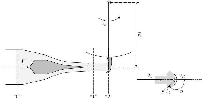
Figure: Key concepts of the Pelton turbine.
Shaft Power
The shaft power \(\dot{W}_s\) produced in the Pelton turbine is:
$$ \dot{W}_s=\dot{m}v_R\left[\delta(u_\delta)\cdot v_1-v_R\right]\left(1-k\cos\beta\right) $$
where:
- \(\dot{m}\) is the mass flow rate through the turbine
- \(v_R = \omega R\) is the reference velocity (\(R\) = radius of rotor where flow hits the bucket, \(\omega\) = angular velocity constrained by grid frequency)
- \(v_1=\frac{\dot{V}}{A_1}\) is water velocity at position "1" (end of nozzle), with \(\dot{V}\) = volumetric flow rate and \(A_1\) = cross-sectional area
- \(\beta\) is the reflection angle (typically \(\beta= 165^{\circ}\))
- \(k<1\) is a friction factor (typically \(k\in[0.8, 0.9]\))
- \(\delta(u_\delta)\) represents deflector mechanism to reduce velocity and avoid over-speed
Total Work and Friction Losses
Total work rate removed through the turbine:
$$ {\dot{W}_t} = {\dot{W}_s+\dot{W}_{ft}} $$
Friction losses:
$$ \dot{W}_{ft}=K\left(1-k\cos\beta\right)\dot{m}v_R^2 $$
with friction coefficient \(K=0.25\).
Nozzle Pressure Drop
Pressure drop across the nozzle (positions "0" and "1"):
$$ \Delta p_n=\frac{1}{2}\rho\dot{V}\left[\dot{V}\left(\frac{1}{A_1^2(Y)}-\frac{1}{A_0^2}\right)+k_f\right] $$
where \(A_0\) is cross-sectional area at nozzle beginning, \(A_1(Y)\) is area at nozzle end (function of needle position Y), and \(k_f\) is the nozzle friction loss coefficient.
Connectors
- TurbineContacts for connection to waterway and electro-mechanical units
- RealInput connector for angular velocity (typically from generator)
Parameters
User specifies: turbine runner radius, nozzle input diameter, runner bucket angle, friction factors and coefficients, deflector mechanism coefficient.
Note: This model has not been tested.
More info in: Resources/Documents/Turbines_model.pdf
Parameters
| Type | Name | Default | Description |
|---|---|---|---|
| SI.Radius | R | 3.3 | Radius of the turbine |
| SI.Diameter | D_0 | 3.3 | Input diameter of the nozzle |
| Real | k | 0.8 | Friction factor |
| Real | k_f | 1 | Coefficient of friction loss in the nozzle |
| Real | K | 0.25 | Friction loss coefficient due to power loss |
| Real | d_u | 1 | Deflector mechanism coefficient |
| Modelica.Units.NonSI.Angle_deg | beta | 165 | |
| Boolean | CompElas | false | If checked the water is compressible and the walls is elastic |
| I/O › Outputs | |||
| Boolean | enable_P_out (from TurbineContacts) | false | If checked, get a connector for the output power |
Connectors
| Type | Name | Default | Description |
|---|---|---|---|
| Contact_i | i (from TwoContacts) | Inlet contact (positive design flow direction is from i to o) | |
| Contact_o | o (from TwoContacts) | Outlet contact (positive design flow direction is from i to o) | |
| Modelica.Blocks.Interfaces.RealInput | u_t (from TurbineContacts) | [Guide vane|nozzle] opening of the turbine(=1: completely open, =0: completely closed) | |
| Modelica.Blocks.Interfaces.RealOutput | P_out (from TurbineContacts) | Mechanical Output power | |
| Modelica.Blocks.Interfaces.RealInput | w_in | Input angular velocity from the generator |
Components
| Type | Name | Default | Description |
|---|---|---|---|
| Data | data | Using standard class with constants | |
| SI.Pressure | p_tr1 | Inlet pressure | |
| SI.Pressure | dp_tr | Turbine pressure drop | |
| SI.Pressure | p_tr2 | Outlet pressure | |
| SI.Pressure | dp_n | Nuzzel pressure drop | |
| SI.Area | A_1 | ||
| SI.Area | A_0 | pi*D_0^2/4 | |
| SI.EnergyFlowRate | Wdot_s | Shaft power | |
| SI.VolumeFlowRate | Vdot | Flow rate | |
| SI.MassFlowRate | mdot | Mass flow rate | |
| SI.Velocity | v_R | ||
| SI.Velocity | v_1 | ||
| SI.AngularVelocity | w | w_in | Angular velocity |
| Real | cos_b | Modelica.Math.cos(Modelica.Units.Conversions.from_deg(beta)) |