
modelAC2DCandDC2AC
Extends from OpenIPSL.Electrical.Essentials.pfComponent (Partial model containing all the parameters for entering power flow data).
Information
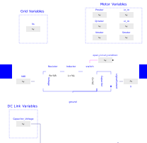
The AC2DCandDC2AC component represents the power electronics component of the variable speed drive. The model provides an interface between two terminals. Terminal pin p is related to the grid bus side and terminal pin n is related to the motor terminal bus. The model is an average representation of the switching components of a real variable speed drive, thus being ideal for long simulation durations on phasor dynamic simulations.
The model has one input and one output connectors. The m_input input connector represents the pwn modulation index, while the Vc output connector represents the capacitor voltage value used in the controller logic block.
The modelling of such devices is based, mainly, on the following reference:
- Panasetsky: Variable Speed Drive Modeling" [Panasetsky2016],
Parameters
| Type | Name | Default | Description |
|---|---|---|---|
| Power flow data | |||
| Types.ApparentPower | S_b (from pfComponent) | SysData.S_b | System base power |
| Types.Voltage | V_b (from pfComponent) | 400e3 | Base voltage of the bus |
| Types.Frequency | fn (from pfComponent) | SysData.fn | System frequency |
| Types.ActivePower | P_0 (from pfComponent) | 1e6 | Initial active power |
| Types.ReactivePower | Q_0 (from pfComponent) | 0 | Initial reactive power |
| Types.PerUnit | v_0 (from pfComponent) | 1 | Initial voltage magnitude |
| Types.Angle | angle_0 (from pfComponent) | 0 | Initial voltage angle |
| Boolean | displayPF (from pfComponent) | false | Display power flow: |
| Parameter mask | |||
| Boolean | enableS_b (from pfComponent) | false | Enable S_b in parameter list |
| Boolean | enableV_b (from pfComponent) | false | Enable V_b in parameter list |
| Boolean | enablefn (from pfComponent) | false | Enable fn in parameter list |
| Boolean | enableP_0 (from pfComponent) | false | Enable P_0 in parameter list |
| Boolean | enableQ_0 (from pfComponent) | false | Enable Q_0 in parameter list |
| Boolean | enablev_0 (from pfComponent) | false | Enable v_0 in parameter list |
| Boolean | enableangle_0 (from pfComponent) | false | Enable angle_0 in parameter list |
| Boolean | enabledisplayPF (from pfComponent) | false | Enable displayPF in parameter list |
| DC Link Parameters | |||
| Modelica.Units.SI.Resistance | Rdc | 0.1 | DC link resistance |
| Modelica.Units.SI.Inductance | Ldc | 0.001 | DC link inductance |
| Modelica.Units.SI.Capacitance | Cdc | 0.02 | DC link capacitance |
| Real | m0 | 0.1 | Initial PWM modulation value |
Connectors
| Type | Name | Default | Description |
|---|---|---|---|
| OpenIPSL.Interfaces.PwPin | p | Grid side pin | |
| OpenIPSL.Interfaces.PwPin | n | Motor side pin | |
| Modelica.Blocks.Interfaces.RealInput | m_input | PWM modulation index input | |
| Modelica.Blocks.Interfaces.RealOutput | Vc | Value of Real output |