blockSrfPLL
Synchronous reference frame phase locked loop
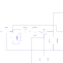
Extends from Modelica.Blocks.Interfaces.MIMO (Multiple Input Multiple Output continuous control block), Interfaces.w_theta (Signal output w and theta).
Information
This phase locked loop works in the synchronous reference frame, also with varying frequency.
The input u[1..2] is the α-β-representation of a threephase signal (after performing the Clarke-transformation), or the cosine and sine signal of an angle sensor.
The output y[1..2] shows the d-q-representation of the input signal.
Parameters
| Type | Name | Default | Description |
|---|---|---|---|
| Integer | nin (from MIMO) | 1 | Number of inputs |
| Integer | nout (from MIMO) | 1 | Number of outputs |
| Real | A0 | 1 | Rated amplitude of input |
| Real | damping | 1/sqrt(2) | Desired damping |
| SI.Time | T | 1e-3 | Desired time constant |
| SI.Frequency | kp | 2*damping/T | Proportional gain |
| SI.Time | Ti | 2*damping*T | Integral time constant |
| Real | epsilon | 1e-3 | Protection aginst division by zero |
| Boolean | useOmegaInput | false | Use input for estimated omega |
| SI.AngularVelocity | wE | 0 | Constant estimated angular velocity |
Connectors
| Type | Name | Default | Description |
|---|---|---|---|
| RealInput[nin] | u (from MIMO) | Connector of Real input signals | |
| RealOutput[nout] | y (from MIMO) | Connector of Real output signals | |
| Modelica.Blocks.Interfaces.RealOutput | w (from w_theta) | Estimated angular velocity | |
| Modelica.Blocks.Interfaces.RealOutput | theta (from w_theta) | Estimated angle | |
| Modelica.Blocks.Interfaces.RealInput | we | estimated angular velocity |
Components
| Type | Name | Default | Description |
|---|---|---|---|
| Modelica.Electrical.Machines.SpacePhasors.Blocks.Rotator | rotator | ||
| Modelica.Blocks.Math.Division | division | ||
| Auxilliary.AddOffset | addOffset | ||
| Modelica.Blocks.Continuous.PI | controller | ||
| Modelica.Blocks.Continuous.Integrator | integrator | ||
| Modelica.Blocks.Math.Abs | abs1 | ||
| Auxilliary.Add | add | ||
| Modelica.Blocks.Sources.Constant | const |