blockInverter1phCurrentController
Simple synchronous reference frame PI current controller
Extends from Modelica.Blocks.Icons.Block (Basic graphical layout of input/output block).
Information
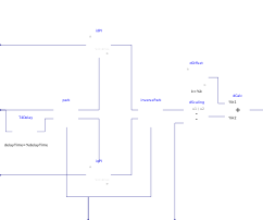
Synchronous reference frame current controller for a 1-phase inverter. It takes the measured and the dq setpoints and calculates the duty cycle, which can be then used as the input to the SignalPWM block in switching models or directly as the input of the switch or converter in averaged models.
The control is performed with two LimPID blocks (one per component) configured as a PI controller.
Parameters
| Type | Name | Default | Description |
|---|---|---|---|
| Real | k | 0.1 | PI controllers gain |
| Modelica.SIunits.Time | T | 0.01 | PI controllers time constant (T>0 required) |
| Modelica.SIunits.Frequency | fline | 50 | AC line frequency |
| Real | idMax | Modelica.Constants.inf | Maximum effort for id loop |
| Real | iqMax | Modelica.Constants.inf | Maximum effort for iq loop |
Connectors
| Type | Name | Default | Description |
|---|---|---|---|
| Modelica.Blocks.Interfaces.RealInput | i | Sensed current | |
| Modelica.Blocks.Interfaces.RealInput | ids | Current d component setpoint | |
| Modelica.Blocks.Interfaces.RealInput | iqs | Current q component setpoint | |
| Modelica.Blocks.Interfaces.RealInput | theta | Sensed AC voltage phase | |
| Modelica.Blocks.Interfaces.RealInput | vdc | Sensed DC voltage | |
| Modelica.Blocks.Interfaces.RealOutput | d | Duty cycle output |
Components
| Type | Name | Default | Description |
|---|---|---|---|
| Park | park | ||
| Modelica.Blocks.Nonlinear.FixedDelay | T4Delay | ||
| Modelica.Blocks.Continuous.LimPID | idPI | ||
| Modelica.Blocks.Continuous.LimPID | iqPI | ||
| InversePark | inversePark | ||
| Modelica.Blocks.Sources.Constant | dOffset | ||
| Modelica.Blocks.Math.Division | dScaling | ||
| Modelica.Blocks.Math.Add | dCalc |